149
Troubleshooting
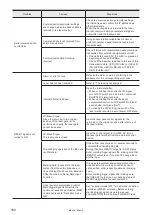
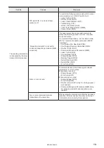
If any operation errors occur, check items below.
When the problems cannot be resolved by following the below measures, please contact our sales office.
Start-up
Troubles
Causes
Measures
Power supply is not
turned on.
The unit does not start
up.
Power cable is not connected.
Connect the power supply cable.
Key switch is not turned on.
Turn on the key switch.
Power is not supplied.
Check the power supply.
Fuse is blown.
Replace the fuse by following the “Safety / Setup
/ Maintenance Guide”.
Laser pumping
Troubles
Causes
Measures
Laser is not pumped.
[IN COM.] [OUT COM.] of terminal
block is not connected to the power
supply.
Connect [IN COM.] and [OUT COM.] in Input/
Output Terminal to internal power supply or
supply power from outside.
The interlock connector is not
connected, or the safety equipment
such as door and switch connected
to the interlock connector is in OPEN
status.
• Check the interlock connector connection.
• Restore the original condition of the safety
equipment connected to the interlock
connector.
Laser stop 2 on input terminal is in
OPEN status, or safety equipment
such as door and switch connected to
the laser stop 2 on input terminal is in
OPEN status.
• Check the connection of [LASER STOP 2A],
[LASER STOP 2B] and [OUT COM.] of input
terminal.
• Restore the original condition of the safety
equipment connected to the laser stop 2.
Emergency stop switch is pressed.
(Except for -LS1 models)
Reset emergency stop switches located on the
controller.
Laser is not pumped in
remote mode.
Laser pumping ON signals from the
external control equipment are not
input or not accepted in remote mode.
• Check connections with external equipment
for mis-connection, disconnection or contact
failure due to any loose connector.
• When controlling the laser pumping by I/O
signal, turn off DIP switch No. 2 and turn on
[LASER IN].
• When controlling the laser pumping by serial
communication, turn on DIP switch No. 2 and
transmit the laser pumping command (LSR).
• To change the DIP setting, the switch of the
laser marker should be set at power OFF state.
ME-LPM-SSM-10
Summary of Contents for LP-M Series
Page 16: ...16 MEMO ME LPM SSM 10...
Page 27: ...27 Chapter 1 Specification ME LPM SSM 10...
Page 37: ...37 Chapter 2 Preparation ME LPM SSM 10...
Page 69: ...Chapter 3 Connection for External Control ME LPM SSM 10...
Page 128: ...Chapter 4 Maintenance ME LPM SSM 10...
Page 148: ...Troubleshooting ME LPM SSM 10...
Page 169: ...Index ME LPM SSM 10...
Page 172: ...172 MEMO No 9000 0066 34V ME LPM SSM 10...
Page 173: ...No 9000 0066 34V...


