38
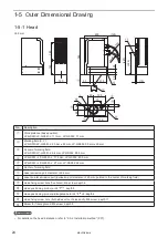
2-3-3 Marking field and marking center position
Specified point
LP-GS051
LP-GS051-L
LP-GS052
A : Work distance
Base position
111 mm
71 mm
Setting range *1
108 mm to 114 mm
–
69.5 mm to 72.5 mm
B : Marking field (X, Y)
55 mm × 55 mm
30 mm × 30 mm
C : Distance to center of marking field
54 mm
50.5 mm
*1 : For models without “-L” in the model code, the work distance (Z-position) may be changed within the extent indicated
in this table.
B
A
B
C
139
Unit: mm
Marking
center
Diameter of laser
output range
φ
66
ワㄐㄕㄊㄆ
• Do not place anything in the area between the laser emission port and work pieces during the lasing operation.
• Use anti-reflection material (ex. black paint for metal) for an external shutter or a protective enclosure in a path of laser
beam. It may cause a failure of the components inside the laser marker head.
• If any other devices such as a sensor or a camera are installed near the laser marker, make sure that these devices are
installed in the place where laser beam and its reflected beam do not damage to them.
ME-LPGS-SM-8
Summary of Contents for LP-GS Series
Page 17: ...1 Product Overview ME LPGS SM 8 ...
Page 32: ...2 Laser Marker Installation ME LPGS SM 8 ...
Page 48: ...3 Operation Method ME LPGS SM 8 ...
Page 68: ...4 External Control Using I O ME LPGS SM 8 ...
Page 107: ...5 External Control by Communication Commands ME LPGS SM 8 ...
Page 116: ...6 Link Control with External Devices ME LPGS SM 8 ...
Page 141: ...7 Maintenance ME LPGS SM 8 ...
Page 161: ...161 MEMO ME LPGS SM 8 ...
Page 162: ...Troubleshooting ME LPGS SM 8 ...
Page 186: ...Index ME LPGS SM 8 ...
Page 189: ......
Page 190: ... Panasonic Industrial Devices SUNX Co Ltd 2014 2019 April 2019 ...

