background image

159

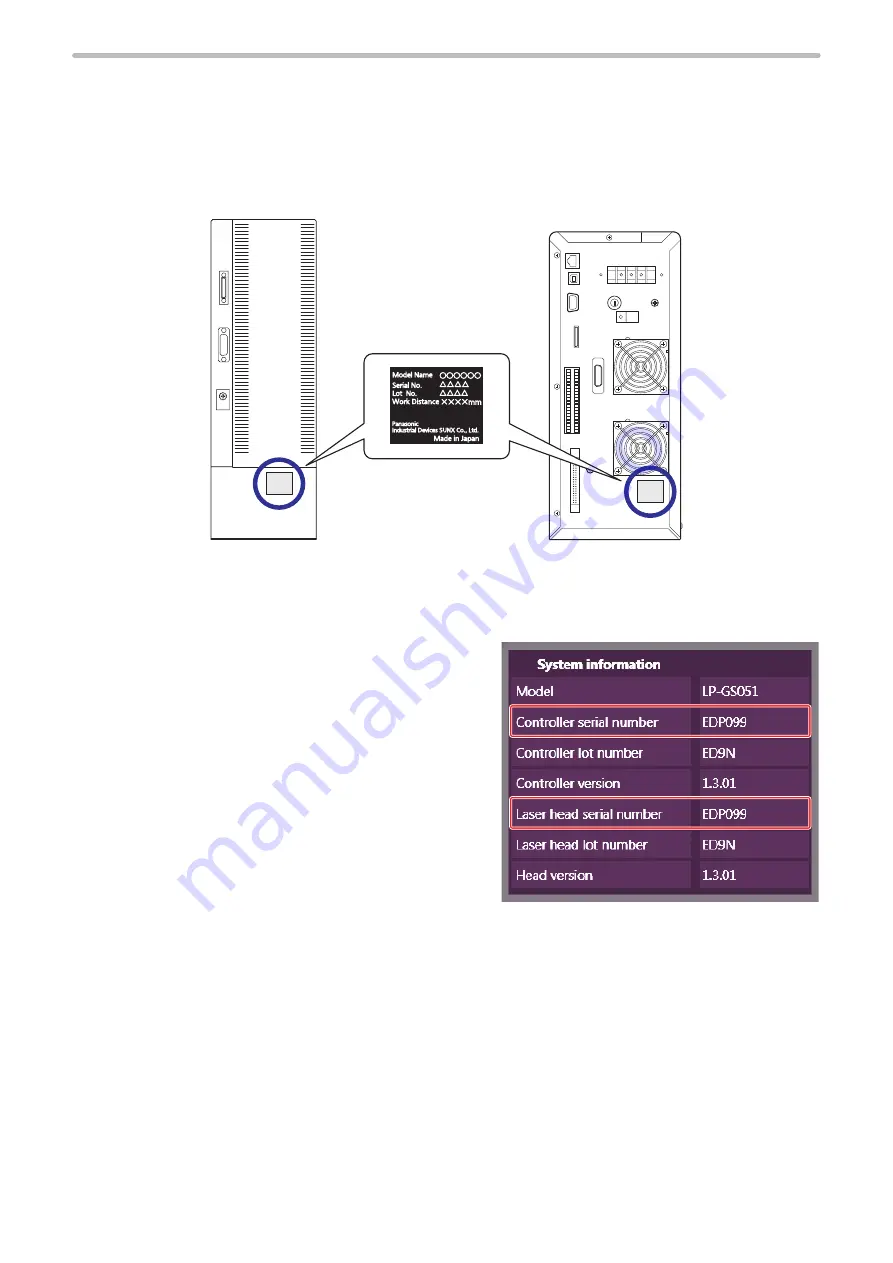
7-4  Serial Number Checking Method

Notify our sales office or representatives of the laser marker serial number for inspection or repair.
The head and controller is delivered with the same serial numbers.


„

Check it on laser marker main unit

The serial number of the laser marker is written on the area marked by a circle in the figure below.

PRD. mm/yyyy

Rear of controller

Rear of head


„

Check it on Laser Marker NAVI smart

Connect the Laser Marker NAVI smart online, and click “Operation/
Information” tab on the “System settings” screen.
Each serial number for the head and controller is displayed on the 
system information panel.

ME-LPGS-SM-8

Summary of Contents for LP-GS Series

Page 1: ...2019 4 panasonic net id pidsx global ME LPGS SM 8 Please read these instructions carefully before using this product and save this manual for future use Laser Marker Setup Maintenance Guide LP GS series ...

Page 2: ...iability for any results arising out of operations regardless of the above clauses Disclaimer The applications described in this document are all intended for examples only The purchase of our products described in this document shall not be regarded as granting of a license to use our products in the described applications We do NOT warrant that we have obtained some intellectual properties such ...

Page 3: ...ructions to be observed This symbol is used to alert users to a specific operating procedure that must not be performed This symbols is used to alert users to a specific operating procedure that must be followed in order to operate the unit safely This symbols is used to alert users to a specific operating procedure that must be performed carefully DANGER Never look at laser beam directly through ...

Page 4: ...r reflectance durability and thermal resistance to enclose the laser radiation area without leakage Construct an interlock systems such as a function to stop laser radiation for the maintenance door of the protective enclosure After power supply of laser marker is turned off laser safety manager must remove the key and keep it Be sure to connect the head and controller of the laser marker which ha...

Page 5: ...nd the laser marker may be generated Dust collector Protective enclosure When using the assist gas for laser processing take safety precautions to protect operators from exposure ignition toxic effect excess or lack of oxygen To carry this product wear the non slip gloves Hold the product with both hands Do not hold the cables or connectors at carrying Install this product in the stable place with...

Page 6: ...hauster near the source of dust or gas Any dust or gas contamination on the laser emission port may cause failure or decrease the laser marking or processing quality In addition when the laser beam is blocked by dust or gas it may cause decrease in laser marking quality Installation To carry this product wear the non slip gloves Hold the product with both hands Do not hold the cables or connectors...

Page 7: ...same electric potential Each connecting cable should not be used in the same raceway or connected in parallel to any device that generates high tension wires power lines large switching surge or the like There is a risk of malfunction caused by induction USB cable should not be connected in parallel with the AC power cable or the motor power cable Make the wiring as short as possible to prevent a ...

Page 8: ...specially require the high level of reliability and safety ACCEPTANCE INSPECTION In connection with the Products you have purchased from us or with the Products delivered to your premises please perform an acceptance inspection with all due speed and in connection with the handling of our Products both before and during the acceptance inspection please give full consideration to the control and pr...

Page 9: ...laser products Equipment classification and requirements 2011 65 EU RoHS Directive EN 50581 2012 Technical documentation for the assessment of electrical and electronic products with respect to the restriction of hazardous substances GB Chinese National Standard GB 7247 1 2012 idt IEC60825 1 2007 激光产品的安全 第 1 部分 设备分类 要求 KC mark Korea Certification 2 Class A Equipment Industrial Broadcasting Communi...

Page 10: ... Guide and safety regulations in each country or region Removing and eliminating dust or gas Depending on the laser radiation objects noxious dust or gas may generate by the laser radiation which could harm human body or the environment Eliminate dust or gas generated using a dust collector or an exhauster according to the constituent of such dust or gas Dispose of the exhaust gas safely and appro...

Page 11: ...authorization from the organization that controls the product conformance the user may lose the right to operate this device Do not install the transmitter of this product loaded onto the head front panel in the same place as the other antennas or transmitters or operate them together To comply with the radio frequency emission limit value of FCC keep 20 cm or more between the antenna head front p...

Page 12: ...tup Maintenance Guide This manual describes the items required for introduction and installation of this product as well as for the maintenance work Product specifications external dimensions Installation and connection method Signal details I O rating and timing chart when I O is used for control Maintenance details Mainly the machine builder and system integrator shall be required for reading th...

Page 13: ...2 2 1 Installation Environment 33 2 2 Installation Space 34 2 3 Head Installation 35 2 3 1 Installation direction 35 2 3 2 Installation method 37 2 3 3 Marking field and marking center position 38 2 3 4 Marking position check 39 2 4 Controller Installation 40 2 5 Connecting Laser Marker 41 2 5 1 Connection of head and controller 41 2 5 2 Power connection and earth Grounding 42 2 5 3 Connection of ...

Page 14: ...t rating and output circuit 86 4 4 3 Interlock terminal rating and I O circuit 87 4 5 Connecting I O Terminal Block 88 4 5 1 Factory default wiring 88 4 5 2 Connecting common terminals 89 4 5 3 Sensor connection example 90 4 5 4 Connection example of interlock terminals and laser stop terminals 90 4 5 5 Checking the I O terminal status 91 4 6 Basic Control Timing Chart 92 4 6 1 Flow from startup t...

Page 15: ...ation settings 121 6 1 5 Set the laser marker overall file conditions 122 6 1 6 Image checker setting 125 6 1 7 Code reader LP ABR setting 129 6 1 8 Code reader DataMan setting 129 6 1 9 Timing chart 130 6 2 Link Control with Code Reader 134 6 2 1 Example of code reader linkage system 134 6 2 2 Operation flow 135 6 2 3 Connection 137 6 2 4 Preparation of readout code 138 6 2 5 Setting of code read...

Page 16: ...umber Checking Method 159 7 5 Disposal of Laser Marker 160 7 5 1 Separate disposal of head section 160 7 5 2 Disposal of old equipment and batteries 160 Troubleshooting 162 Troubleshooting 163 Error Indication 173 Alarm E001 E599 173 Warning E600 E799 177 Index 186 ME LPGS SM 8 ...

Page 17: ...1 Product Overview ME LPGS SM 8 ...

Page 18: ...e laser output class and the marking field size The following types are applicable to this product 051 Laser output 5W Marking field 55 mm x 55 mm 052 Laser output 1 3W Marking field 30 mm x 30 mm e Represents the existence of the Z axis control function None Left justified A model with the Z axis control function L A model without the Z axis control function r Represents the existence of the Blue...

Page 19: ...and set the marking data of the laser marker You can use this PC as a monitor during the operation u Laser Marker Smart Utility software Attached CD ROM This software contains the laser marker configuration software Laser Marker NAVI smart and PDF manual data Optional items The following optional items sold separately are available for this product For purchasing and the detailed information pleas...

Page 20: ...reuse the packing materials to prevent damages during transportation Laser marker head 1 unit Laser marker controller 1 unit System key Unit power cable Signal cable AC power cable 1 qty 2 qty 1 qty 1 qty 1 I O terminal block Short bar Attached to the I O terminal block USB cable 2m Ferrite core Laser Marker Smart Utility CD ROM 3 qty 1 qty 6 qty 1 qty 1 2 qty 1 Laser Safety Guide Leaflet of carry...

Page 21: ...guration software Laser Marker NAVI smart Logo Data Editing Software ExportVec Font Maker PDF manuals Language Laser Safety Guide English Simplified Chinese Japanese Setup Maintenance Guide Serial Communication Command Guide Serial Communication Command Guide LP 400 V compatible mode Laser Marker NAVI smart Operation Manual Logo Data Editing Software Operation Manual ExportVec Operation Manual Fon...

Page 22: ...ned characters up to 50 characters can be set Japanese characters Katakana Hiragana Kanji JIS level 1 and level 2 Simplified Chinese characters GB 2312 level 1 and level 2 Bar code CODE39 CODE93 CODE128 GS1 128 ITF NW 7 EAN UPC JAN GS1 DataBar Limited GS1 DataBar Stacked GS1 DataBar Limited CC A GS1 DataBar Stacked CC A 2D code QR Codes Micro QR Codes iQR Codes Data Matrix GS1 Data Matrix PDF417 G...

Page 23: ...ivery time with the maximum laser power setting 2 The work distance base position has approx 0 5mm deviation per product 3 The value shown here is the configuration range that can be input The setting values that can keep the quality of marking or processing vary depending on the setting details and the target materials 4 VEC is a graphic file format dedicated for the laser marker To use AI or EPS...

Page 24: ...51 L 77 5 mm LP GS052 69 5 mm t LP GS051 LP GS051 L 27 mm LP GS052 24 mm y Center of marking field u Laser emission port diameter φ94 mm i Laser pointer emission port Emission port diameter φ20 mm pointed to the center of marking field o Head fixing screw hole five holes M6 screw depth 6 1 Head positioning pin hole φ4 0 012 0 depth 5 1 Head positioning pin hole Elongated hole φ4 0 05 0 5 depth 5 1...

Page 25: ...0 39 183 51 287 340 250 95 25 q w e q No Description q Controller fixing screw hole four holes each on the bottom and the left side on the front M5 screw depth 6 w Protective conductor terminal M4 screw depth 5 e Screw for frame ground M4 screw depth 5 ME LPGS SM 8 ...

Page 26: ...tandards and CSA UL standards compatible cable North America Japan Included in LP GS051 L F LF LP GS052 F w Rating 250V VDE standards compatible cable Europe Included in LP GS051 L F LF E LP GS052 F E e Rating 250V CCC standards compatible cable China Included in LP GS051 L FN LP GS052 FN Unit mm Minimum bent radius 50mm 3000 100 q w e ワㄐㄕㄊ ㄆ Be sure to connect the ground pin of the AC power cable...

Page 27: ... Laser pumping uncompleted Shutter CLOSE White flashing Laser non pumping status Lights off w ALARM WARNING Alarm Red lighted up Warning Yellow lighted up e REMOTE Remote mode operation by external control state Green lighted up r NOTICE This indicator is non operational system reserved t PC LINK Connected to Laser Marker NAVI smart online Green lighted up y FILE No ERROR CODE Normal Displays the ...

Page 28: ...rt of the marking laser and the guide laser for LP GS051 L 6 Laser pointer emission port From this port the red laser pointer radiates in oblique direction for the guide pointer function The pointer radiates also when using the work distance indication by the guide laser for LP GS051 L Refer to 2 3 4 Marking position check P 39 To use these guide laser functions do not seal the laser pointer emiss...

Page 29: ...erval five seconds or more between ON and OFF Do not turn off the power supply while the system starts during MAIN indicator is flashing 2 Controller indicator The indicator that shows the status of the laser marker No Display name Status Indication q MAIN System startup state Green lighted up System starting up not completed Green flashing w LASER Laser pumping status White lighted up Laser pumpi...

Page 30: ...control of the laser marker using RS 232C PLC or PC for control Externally controls the laser marker using the communication commands Code reader compatible with the RS 232C communication Modifies the data to mark by the laser marker according to the code details read by the code reader 4 Signal connector SIGNAL This is the terminal for communicating between head and controller Connect the attache...

Page 31: ...ltage and frequency are switched automatically ワㄐㄕㄊ ㄆ Be sure to connect the ground pin of the AC power cable to earth permanently Refer to 2 5 2 Power connection and earth Grounding P 42 10 Fuse holder FUSE 250V T 10A Rotate and remove holder for replacing the fuse on fusing For details refer to 7 2 10 Replacement of fuse P 157 11 Protective conductor terminal This is the terminal for ground Grou...

Page 32: ...2 Laser Marker Installation ME LPGS SM 8 ...

Page 33: ...ations and shocks can be directly transmitted to it Do not use this product at a place with oil mist In case this product is used in a dusty environment take measures to prevent dust from entering into the laser marker e g using a storage housing When installing the laser marker in the storage housing use a housing equipped with panel cooler or heat exchanger to maintain the air cooling performanc...

Page 34: ...ntain the air cooling performance of the laser marker install both the head and controller in a well ventilated place Installing near a heating element could cause the ambient temperature exceeding the specification range which may cause malfunction of the product When setting more than one laser marker install them so that a space of 300 mm or more is given between the heads of each marker Not do...

Page 35: ...port 2 3 1 Installation direction The head can be installed to up down left and right directions To install the product with the laser emission port facing upward or horizontally fix both right and left sides with the bottom surface laser emission port side used as installation surface by using screw holes on the head side ワㄐㄕㄊ ㄆ When the product is installed with the laser emission port facing up...

Page 36: ...ped without vibration Radiating laser during movement or right after stopping will cause marking disorder Controller s vibration resistance only applies when without current Do not move it during operations Secure at least 100mm bend radius for the cable Install the product so that no load is applied onto the cable Do not wire the cable with load locally put on the cable Do not wire the cable with...

Page 37: ...her thickness Laser marker head Installation plate ワㄐㄕㄊ ㄆ Do not insert any screw of length exceeding the specification Otherwise the failure of the product may be caused Example of head installation base Example dimensions of plate for the head are indicated below For plate thickness of 10 mm Unit mm 120 φ20 60 10 5 q e r 40 60 120 60 w φ94 On the laser marker side No Description q Head fixing ho...

Page 38: ... table B A B C 139 Unit mm Marking center Diameter of laser output range φ66 ワㄐㄕㄊ ㄆ Do not place anything in the area between the laser emission port and work pieces during the lasing operation Use anti reflection material ex black paint for metal for an external shutter or a protective enclosure in a path of laser beam It may cause a failure of the components inside the laser marker head If any o...

Page 39: ... field frame and center lines with the guide laser Marking image 1 Displays the setting data in the file The object data with marking off setting is not displayed Masked objects 1 Displays only the data set to Marking off and enabled guide indication Work distance 1 The guide laser shows the rough indication of the work distance distance from the head base to the marking surface The red point emit...

Page 40: ...sure that the key switch side is at the bottom For details of installation refer to 1 5 2 Controller P 25 Fix the controller in the following conditions Fixing surface Fixing screw Screw insert length Tightening torque Bottom M5 screws at 4 positions 6 mm or below 2 0 N m or below Side front left side M5 screw M5 screw ワㄐㄕㄊ ㄆ Do not insert any screw of length exceeding the specification Otherwise ...

Page 41: ... them without excess forces being applied q w e Rear of head Rear of controller No Cable and connector Connector q Signal cable Signal connector SIGNAL w Unit power cable Power connector POWER e I O terminal block I O terminal block connector TERMINAL ンㄆㄇㄆㄓㄆㄏ ㄆ Connect the following terminals of the I O terminal block If any of them is not connected the laser radiation is disabled When shipped the...

Page 42: ...rform the connection of the Power Terminal with power off state Failure to do so may cause electrical shock 1 Connect the protective conductor terminal and the frame ground terminal to the grounding part Screw size M4 Tightening torque 1 0N m ワㄐㄕㄊ ㄆ Before connecting the power supply connect the protective conductor terminal and the frame ground terminal permanently to the grounding part Install s...

Page 43: ...he clamp Screw size M4 Tightening torque 1 0N m ワㄐㄕㄊ ㄆ Locate the AC power cable beside the fan Locating it in front of the fan may impair the air cooling performance leading to the device failure 7 Make sure that the cables and connectors other than the power supply are connected and then connect the AC power cable to the AC power supply Power voltage 90V to 132V AC or 180V to 264V AC including 1...

Page 44: ...ended support are excluded The CPU type memory capacity hard disk space and display function required to operate each OS should be provided in accordance with the recommendation of Microsoft Laser Marker NAVI smart can be installed in English German Simplified Chinese or Japanese It is preferred that the OS language corresponds to the installation language If the OS language is other than these su...

Page 45: ...ion P 56 q USB connection Connect the attached USB cable to the USB port B on the controller Multiple laser markers can be connected via a USB hub etc ワㄐㄕㄊ ㄆ Do not disconnect the USB cable when the laser marker is connected online w Ethernet connection Connect the LAN cable to the Ethernet port on the controller For details of specifications and connection of the Ethernet port refer to 5 3 Ethern...

Page 46: ...luetooth function of this product can be used refer to Using Bluetooth wireless terminal equipment P 11 This product does not guarantee connections and operations with every Bluetooth ready device Bluetooth usage may be restricted depending on the ambient situation or environment Check with the administrator or the manager of the building if using Bluetooth is allowed before using the Bluetooth fu...

Page 47: ...Besides INTERLOCK terminals it can also be connected to other I O signals such as LASER STOP terminals with the devices t to i depending on the control specifications 1 Laser radiation warning light To indicate the laser marker status connect the output signals such as ALARM OUT Y15 or LASING OUT Y20 to the light 1 Dust exhauster Place the intake vent of the exhauster as close as possible to the m...

Page 48: ...3 Operation Method ME LPGS SM 8 ...

Page 49: ... connected to I O terminal Clicking the marking start button of the Laser Marker NAVI smart screen Use this operation mode to configure the laser marker without using the external control devices as PLC ンㄆㄇㄆㄓㄆㄏ ㄆ Refer to 3 3 6 Test marking and RUN mode P 61 You can edit marking data with Laser Marker NAVI smart even when it is not connected to the laser marker offline For the operation method of ...

Page 50: ... ON the key switch of the controller The MAIN power indicator of the controller flashes 3 The system startup completes approximately after 10 seconds The MAIN power indicator of the controller changes from blinking light to steady light ワㄐㄕㄊ ㄆ Do not set the key switch to OFF until system startup has been completed In case of turning ON the power supply after turning OFF leave the interval five se...

Page 51: ...e sure to check the file saving before turning off the power For details on the operation method please refer to the Laser Marker NAVI smart Operation Manual 3 Disconnect the online connection Refer to 3 3 4 How to disconnect online connection P 58 ワㄐㄕㄊ ㄆ Do not turn the laser marker power OFF while being connected to online When the power gets turned OFF during data communication it may cause the...

Page 52: ... marker etc ンㄆㄇㄆㄓㄆㄏ ㄆ Only one unit of laser marker can be connected to Laser Marker NAVI smart online at once If more than one laser marker is connected to one PC switch the laser marker connected online using Laser Marker NAVI smart to configure control each laser marker 3 3 1 Operation procedure Offline editing Operation example from offline editing to laser marker data registration On the star...

Page 53: ...r click the marking start button of Laser Marker NAVI smart Turn ON key switch of laser marker controller Start up the Laser Marker NAVI smart Edit the file Start test marking Save the file Edit and save the file Start RUN mode operation Marking trigger input Select file to use in RUN mode operation Screen selection Select a file to edit Laser pumping ON Shutter open automatic Laser radiation Turn...

Page 54: ... you verify the operation status of the laser marker with the remote mode control or during the RUN mode Main usages Check the marking image Check the settings Check the ON OFF state of I O Marking settings This is the screen where you configure and edit the marking data file Main usages Create new marking data Edit the marking data individual files or backup file saved in external device or local...

Page 55: ... a power meter available in stores Data management This is the screen where you back up add or delete data saved in the laser marker Main usages Add delete a marking file graphic data or font Acquire the backup of data saved in the laser marker Restore the backup data to the laser marker System settings This is the screen where you configure the laser marker operation settings system clock and com...

Page 56: ...le or LAN cable while the online connection with the laser marker is active Do not turn the laser marker power OFF while being connected to online ンㄆㄇㄆㄓㄆㄏ ㄆ If PC goes into Sleep when the laser marker and PC are connected online the online connection between them is disabled If PC goes into sleep state in the REMOTE mode or RUN mode the PC is disconnected but the operation state of the laser marke...

Page 57: ...work For Bluetooth Enabled the Bluetooth communication 3 Click Set on the lower right corner of the screen 4 Disconnect the laser marker and Laser Marker NAVI smart from online and exit Laser Marker NAVI smart 5 Turn the laser marker power OFF and wait for at least five seconds and then turn it ON 6 Start Laser Marker NAVI smart and verify that either Ethernet or Bluetooth connection marker appear...

Page 58: ...power OFF 1 Click Select Laser Marker Status Display tool located on the upper left corner of the screen to display the Select Laser Marker window 2 Click X located on the upper right corner of the laser marker icon displayed at Laser marker connected Disconnect the online connection with the laser marker ME LPGS SM 8 ...

Page 59: ...When password is forgotten If you have configured the password on the system settings screen you are required to enter the password when you switch from Monitor Operator settings or Maintenance screen to Marking settings Data management or System settings screen If you have forgotten this password delete the password according to the following procedure 1 If the laser marker is in the remote mode ...

Page 60: ... then click OK ワㄐㄕㄊ ㄆ If Clear the password remains enabled the password will be deleted when connected to online even without executing ClearPassword exe Make sure to uncheck the box next to Clear the password 8 To reconfigure the password start Laser Marker NAVI smart and select System settings on the screen selection menu Display the Access premissions panel and enter the password for screen sw...

Page 61: ...nfirmation dialog box of the laser radiation appears Click Yes to start radiating the laser RUN mode procedure The RUN mode is an operating method of radiating the laser by external control or by the marking start signal from Laser Marker NAVI smart while the laser marker is in the marking start signal standby state 1 Select any of the following screens Marking settings Operator settings Monitor 2...

Page 62: ...P 61 External control remote mode by serial communication commands RS 232C Ethernet To control the laser marker by communication commands from external devices such as PLC use RS 232C or Ethernet connection For details refer to 5 External Control by Communication Commands P 107 and Serial Communication Guide External control device RS 232C or Ethernet Laser marker controller ンㄆㄇㄆㄓㄆㄏ ㄆ It is availa...

Page 63: ...trol OPEN shutter Remote mode ON Select file Confirm READY OUT is ON Trigger Input ON Laser pumping ON Control by using I O or communication commands ンㄆㄇㄆㄓㄆㄏ ㄆ It is available to the external control combining I O and serial communication commands You need to configure the system settings on the I O communication in advance before using external control Refer to 3 4 3 Settings before external cont...

Page 64: ...itial setting 6 Select the control method for the following operations between I O or communication commands As the default I O control is selected to all settings Laser pumping control Shutter control Guide laser control LP GS051 L type only ンㄆㄇㄆㄓㄆㄏ ㄆ To use Laser Radiation for Measurement Command SPT of the serial communication commands set the shutter control method to communication commands Fo...

Page 65: ...STOP 1 IN or LASER STOP 2 IN Initial setting LASER STOP 2 IN For the operation details of LASER STOP refer to Laser marker operation when functions for safety measures are input P 77 One shot pulse duration Configure the output time of the signal being output as one shot such as PROCESSING END OUT Y11 Setting range 2 to 510ms initial value is 40ms 10 Click the Set button on the lower right corner ...

Page 66: ...ries refer to the Serial Communication Command Guide LP 400 V compatible mode Encoding for 2 byte characters is used for the Japanese and Chinese characters which cannot be specified by the ASCII codes To use Japanese set Shift JIS and for simplified Chinese set GB 2312 13 To input the control codes in the barcode 2D code strings using the communication commands click Details of Input method for c...

Page 67: ...Use the remote mode switch button of Laser Marker NAVI smart for releasing and resetting the remote mode ンㄆㄇㄆㄓㄆㄏ ㄆ If you want to start up the laser marker in the remote mode you need to configure the settings on the system settings screen of Laser Marker NAVI smart in advance If you have configured the laser marker to start up in the remote mode you cannot switch the remote mode from I O Remote m...

Page 68: ...4 External Control Using I O ME LPGS SM 8 ...

Page 69: ...Rear of controller I O terminal block I O connector Laser marker Hook The I O terminal block can be removed by holding down the hooks Connector specifications and models Connector position Connector specifications Model Manufacturer name I O terminal block On the laser marker side Dedicated connector DMC1 5 20 GIF 3 5 LR P20THR Phoenix Contact Company User side Accessories DFMC1 5 20 ST 3 5 LR I O...

Page 70: ...COM 1 Output common 1 Y3 24V OUT Internal power 24V Y4 REMOTE OUT Y5 READY OUT Y6 LASER STANDBY OUT Y7 SYSTEM STANDBY OUT Y8 SHUTTER OPEN 1 OUT Y9 SHUTTER OPEN 2 OUT Y10 PROCESSING OUT Y11 PROCESSING END OUT Y12 PROCESSING FAIL OUT Y13 RESERVE System reservation Y14 WARNING OUT Y15 ALARM OUT Y16 INTERLOCK 1 MONITOR Y17 INTERLOCK 1 MONITOR COM Y18 INTERLOCK 2 MONITOR Y19 INTERLOCK 2 MONITOR COM Y20...

Page 71: ...t is turned on the laser marker operates in the remote mode which can be controlled externally by I O and serial communication commands To transit to the remote mode using this terminal you will need to configure the communication setting of Laser Marker NAVI smart in advance Refer to 3 4 4 Remote mode settings P 67 X5 TRIGGER IN Marking trigger input The signal to start marking laser radiation St...

Page 72: ...functions for safety measures are input P 77 Terminal connection Status when the terminal is open Shutter Laser pumping LASER STOP 1 IN OUT COM 1 Laser is not radiating Close Hold ON Radiating the laser Close OFF LASER STOP 2 IN OUT COM 1 The same operation at all times Close OFF For X11 you can select its behavior from LASER STOP 1 IN or LASER STOP 2 IN by the setting of LASER MARKER NAVI smart I...

Page 73: ... the double circuit of the interlock can be constructed INTERLOCK connection Shutter Laser pumping X16 X17 Open Close OFF X18 X19 Open ワㄐㄕㄊ ㄆ INTERLOCK terminals X16 X17 and X18 X19 are connected to the operating coil of the internal relay in the controller Connect INTERLOCK and INTERLOCK with the non voltage contact dry contact such as a relay or a switch Do not connect with the voltage contact s...

Page 74: ...ply for the external device and the consumption current for the I O control should be less than 300mA Y4 REMOTE OUT Remote mode output The output is ON during the remote mode Make sure that this terminal is turned ON and start the external control by I O or serial communication commands Y5 READY OUT Marking trigger ready output When TRIGGER IN X5 becomes acceptable the laser radiation becomes read...

Page 75: ...duration of the trigger delay time and LASING OUT Y20 If you are using the link function with external devices output time of PROCESSING OUT Y10 includes operation time of the external device laser radiation time and internal processing time of the laser marker Y11 PROCESSING END OUT Trigger processing completed output Output ON when the input marking trigger processing such as laser radiation is ...

Page 76: ...E Short circuited Y18 Y19 OPEN Interlock monitor is switched open and closed with a delay of approx 20ms with reference to each interlock input as shown below 20ms 20ms INTERLOCK INTERLOCK X16 X17 X18 X19 INTERLOCK MONITOR INTERLOCK MONITOR COM Y16 Y17 Y18 Y19 CLOSE OPEN CLOSE OPEN Y20 LASING OUT Laser radiation output Output ON during laser radiation In case the lasing time is shorter than the se...

Page 77: ...re control LASER STOP 1 IN X10 X11 1 Opened during laser emission Laser Pumping OFF Internal Shutter CLOSE Status Alarm E402 Close LASER STOP 1 IN connection and input alarm reset The power supply of laser source is shut down through the internal circuit by the software control Opened at non emitting with opened shutter Laser Pumping Hold ON Internal Shutter CLOSE Status Warning E600 Close LASER S...

Page 78: ...TIMING IN 25 RESERVE System reservation 26 No Name 27 OUT COM 2 Output common 2 28 SET OK OUT 29 DATE GAP OUT 30 COUNT END A OUT 31 COUNT END B OUT 32 COUNT END C OUT 33 COUNT END D OUT 34 CHECK OK OUT 35 CHECK NG OUT 36 TIMING WAIT OUT 37 SCRIPTING OUT 38 N C Not connected 39 N C Not connected 40 N C Not connected ンㄆㄇㄆㄓㄆㄏ ㄆ IN COM 1 OUT COM 1 of the I O terminal block and IN COM 2 OUT COM 2 of th...

Page 79: ...ng of the edge of turning ON SET IN is required to control the following operations by I O Select file number Correct the count up count down value of the counter function Reset the count value of the counter function Switch marking characters of the registered characters via I O Switch marking position of the external offset function 3 to 18 D0 IN to D15 IN Number input Set the number for one of ...

Page 80: ...t binary system by specifying ON OFF of D8 to D15 as shown in the below table D0 to D7 Counter No 0 to 3 16 to 19 Terminal Counter No Input D0 0 OFF D1 1 OFF D2 2 OFF D3 3 ON D4 16 OFF D5 17 OFF D6 18 OFF D7 19 OFF D8 to D15 Step times Terminal Step times binary Input D8 0 OFF D9 1 ON D10 0 OFF D11 0 OFF D12 0 OFF D13 0 OFF D14 0 OFF D15 0 OFF Counter No 16 to 19 are the common counters you can us...

Page 81: ...aracter table 2 0 to 15 D12 to D15 Registered character table 3 0 to 15 Registered characters 8 bit 2 D0 to D7 Registered character table 0 0 to 255 D8 to D15 Registered character table 1 0 to 255 External offset Lower 4 bits D0 to D3 External offset 0 to 15 External offset Lower 8 bits D0 to D7 External offset 0 to 255 External offset Lower 10 bits D0 to D9 External offset 0 to 1023 You can also ...

Page 82: ...d date of the system clock at the point when the input was turned ON then it marks the functional characters for current date expiry date and lot TIME HOLD IN is available even when the remote mode is turned off If TIME HOLD IN is turned ON when powering on the laser marker it retains the system startup time 23 For LP GS051 L type GUIDE IN Guide laser radiation input The guide laser irradiates whi...

Page 83: ...s the output to notify you that the laser marker is marking the different date from that of the system clock while TIME HOLD IN is turned ON 30 31 32 33 COUNT END A OUT Counter end A output COUNT END B OUT Counter end B output COUNT END C OUT Counter end C output COUNT END D OUT Counter end D output Each output turns ON when the count value of the specified counter numbers has marked the end value...

Page 84: ...he image checker is configured This terminal turns ON while executing scripting laser marker s internal processing to perform the link control of the external devices upon receiving TRIGGER IN X5 The output time of SCRIPTING OUT does not include the laser radiation time 38 N C Not connected Do not connect externally 39 N C Not connected Do not connect externally 40 N C Not connected Do not connect...

Page 85: ...y 24V DC External power supply 24V DC NPN open collector output PNP open collector output Each input Each input ワㄐㄕㄊ ㄆ This product supports both the NPN transistor output and the PNP transistor output However the wiring from I O terminal block and the I O connector respectively cannot be used as NPN PNP mixed Operate the product after selecting either NPN or PNP Do not short circuit 24V OUT X1 Y3...

Page 86: ...ad Each output ワㄐㄕㄊ ㄆ This product supports both the NPN transistor output and the PNP transistor output However the wiring from I O terminal block and the I O connector respectively cannot be used as NPN PNP mixed Operate the product after selecting either NPN or PNP Do not short circuit 24V X1 Y3 and 0V Y1 X3 Also do not short circuit IN COM 1 X2 and OUT COM 2 Y2 X12 Starting the laser marker wi...

Page 87: ...s a relay or a switch Do not connect with the voltage contact such as a transistor Pin X16 INTERLOCK 1 ヌビフヷチュヤ ヒブㄎモチ ヌビフヷチュヤ Pin X17 INTERLOCK 1 Pin X18 INTERLOCK 2 Pin X19 INTERLOCK 2 Pin Y16 INTERLOCK 1 MONITOR Pin Y17 INTERLOCK 1 MONITOR COM Pin Y19 INTERLOCK 2 MONITOR COM Pin Y18 INTERLOCK 2 MONITOR ヒブㄎモチ Laser marker internal circuit Safety relay Safety relay Laser oscillator power Contact ca...

Page 88: ...X2 X3 X4 X5 X6 X7 X8 X9 X10 X11 X12 X13 X14 X15 X16 X17 X18 X19 X20 Y1 Y2 Y3 Y4 Y5 Y6 Y7 Y8 Y9 Y10 Y11 Y12 Y13 Y14 Y15 Y16 Y17 Y18 Y19 Y20 Short circuited Short circuited Short circuited Short circuited Short circuited Short circuited I O terminal block 1 For X11 you can select its behavior from LASER STOP 1 IN or LASER STOP 2 IN by the setting of LASER MARKER NAVI smart Initial setting LASER STOP...

Page 89: ...y the external power such as PLC do not connect anything to the internal power 24V OUT X1 Y3 or 0V OUT X3 Y1 of the I O terminal block If a short bar is installed remove it ンㄆㄇㄆㄓㄆㄏ ㄆ IN COM 1 and OUT COM 1 of the I O terminal block are independent from IN COM 2 and OUT COM 2 of the I O connector If you use the I O connector terminal connect input common output common of the I O terminal block and ...

Page 90: ...K1 MONITOR COM INTERLOCK2 MONITOR INTERLOCK2 MONITOR COM INTERLOCK1 INTERLOCK1 INTERLOCK2 INTERLOCK2 LASER STOP 2 IN LASER STOP 1 IN 1 LASER STOP 1 IN OUT COM 1 N O 3 3 2 2 N O X8 X9 X10 X11 X12 X13 X14 X15 X16 X17 X18 X19 X20 Y8 Y9 Y10 Y11 Y12 Y13 Y14 Y15 Y16 Y17 Y18 Y19 Y20 I O terminal block Monitor 2 Monitor 1 Input to PLC 1 For X11 you can select its behavior from LASER STOP 1 IN or LASER STO...

Page 91: ... is updated every 500ms There is a margin of error between the actual input output time and the ON OFF time displayed on the screen Output simulation With the output simulation you can check the output signals of the laser marker without an actual operation Use this function to confirm the operation of the external devices connected with the laser marker Output simulation starts with the following...

Page 92: ...F ON OFF ON OFF ON OFF ON OFF ON OFF ON OFF ON OFF ON OFF ON OFF ON OFF ON OFF ON OFF Open Close ON OFF Open Close ON OFF Normal Error ON OFF Normal Error REMOTE IN X4 1 LASER SUPPLY IN X6 SHUTTER ENABLE IN X9 SHUTTER IN X8 TRIGGER IN X5 SYSTEM STANDBY OUT Y7 REMOTE OUT Y4 LASER STANDBY OUT Y6 ALARM OUT Y15 WARNING OUT Y14 READY OUT Y5 PROCESSING OUT Y10 LASING OUT Y20 PROCESSING END OUT Y11 SHUTT...

Page 93: ...e Total time for shutter opening T3 and marking data creation It varies depending on the quantity of the setting data When the laser pumping is not completed Total time for shutter opening T3 and marking data creation or time for laser pumping whichever is longer T5 2ms or more Keep the ON status for 2ms or more T6 When TRIGGER IN X5 is accepted PROCESSING OUT Y10 turns ON The output time of PROCE...

Page 94: ... of SHUTTER OPEN 1 OUT Y8 and SHUTTER OPEN 2 OUT Y9 SHUTTER OPEN 1 OUT and SHUTTER OPEN 2 OUT will be output by the same operation but their output timing has a margin of error T2 Total time for shutter opening T1 and marking data creation It varies depending on the quantity of the setting data T3 2ms or more Keep the ON status for 2ms or more T4 When TRIGGER IN X5 is accepted PROCESSING OUT Y10 t...

Page 95: ...s completed If you are not using the link function with external devices output time of PROCESSING OUT Y10 is almost the same as the total duration of the trigger delay time and LASING OUT Y20 T3 0 to 9999ms When the trigger delay time is set in the selected file trigger processing lasing operation starts after the delay time T4 2 to 510ms This is the output to notify that the marking trigger proc...

Page 96: ...rks T1 2 ms or more Keep the ON status for the duration of repeating the lasing operation T2 0 to 9999 ms When the trigger delay time is set in the selected file trigger processing lasing operation starts after the delay time T3 0 0 to 60 0 sec When the scanning interval is set the next lasing operation starts after a lapse of the setting period T4 2 to 510 ms This is the output to notify that the...

Page 97: ...fter a lapse of the setting period T4 2 to 510 ms This is the output to notify that the marking trigger processing completed normally This is One shot output Set the output time on the system settings screen There is a small margin of error for the setting value When the marking operation stops halfway because TRIGGER IN turns OFF it is treated as normal operation end T5 Time for marking data crea...

Page 98: ...aser is stopped automatically after passing 1 minute from start up 1 Select the indication contents of the guide laser with SELECT 0 IN to SELECT 2 IN as follows Radiation details SELECT 0 IN No 19 SELECT 1 IN No 20 SELECT 2 IN No 21 Work distance OFF OFF OFF Marking image ON OFF OFF Marking field OFF ON OFF Masked objects ON ON OFF 2 Keep the input state of SELECT 0 IN to SELECT 2 IN No 19 21 whi...

Page 99: ... margin of error for the setting value T4 In the laser pumping completed and shutter opened state Time for marking data creation It varies depending on the quantity of the setting data When the laser pumping is not completed and shutter is closed Total time for shutter opening and marking data creation or time for laser pumping whichever is longer T5 2ms or more Keep the ON status for 2ms or more ...

Page 100: ...ned regardless of the file number remote mode ON OFF status or error status If you turn on off TIME HOLD IN No 22 continuously keep the OFF time at least for two seconds 4 6 8 Counter end output T1 T1 T1 T1 ON OFF ON OFF ON OFF ON OFF PROCESSING OUT Y10 COUNT END A B C D OUT No 30 31 32 33 TRIGGER IN X5 READY OUT Y5 Mark the counter end value Item Time Remarks T1 2ms or more Keep the ON status for...

Page 101: ... value T4 0ms or more Turn on TRIGGER IN X5 after SET OK OUT No 28 turns on T5 2ms or more Keep the ON status for 2ms or more 1 Select the number input target with SELECT 0 IN to SELECT 2 IN as follows Number input target SELECT 0 IN No 19 SELECT 1 IN No 20 SELECT 2 IN No 21 Count up value correction OFF ON OFF Count down value correction ON ON OFF 2 Select a value from D0 to D7 for the counter nu...

Page 102: ... of error for the setting value T4 0ms or more Turn on TRIGGER IN X5 after SET OK OUT No 28 turns on T5 0 5ms or more After a lapse of 0 5ms or more from specifying SELECT 0 IN to SELECT 2 IN and D0 IN to D15 IN turn on SET IN No 2 1 To reset the counter set SELECT 0 IN to SELECT 2 IN as follows SELECT 0 IN No 19 OFF SELECT 1 IN No 20 OFF SELECT 2 IN No 21 ON 2 Specify the counter number to reset ...

Page 103: ...g data compiling has finished within the trigger processing time 1ms or less When the next marking data compiling did not finish within the trigger processing time The remaining time of the marking data compiling T4 1 To specify the registered characters external offset data number set SELECT 0 IN to SELECT 2 IN as follows SELECT 0 IN No 19 ON SELECT 1 IN No 20 OFF SELECT 2 IN No 21 OFF 2 Specify ...

Page 104: ...FF Error Marking interruption Item Time Remarks T1 Max 1 sec There is a delay time of around 200ms to max 1 second from turning ON OFF of SHUTTER IN X8 to turning ON OFF of SHUTTER OPEN 1 OUT Y8 and SHUTTER OPEN 2 OUT Y9 SHUTTER OPEN 1 OUT and SHUTTER OPEN 2 OUT will be output by the same operation but their output timing has a margin of error T2 Total time for shutter opening and marking data cre...

Page 105: ...4 T4 T3 T5 Marking interruption Item Time Remarks T1 Max 1 sec There is a delay time of around 200ms to max 1 second from turning ON OFF of SHUTTER IN X8 to turning ON OFF of SHUTTER OPEN 1 OUT Y8 and SHUTTER OPEN 2 OUT Y9 SHUTTER OPEN 1 OUT and SHUTTER OPEN 2 OUT will be output by the same operation but their output timing has a margin of error T2 100ms or more Keep the ON status for 100ms or mor...

Page 106: ... CLOSE OPEN ON OFF Marking interruption Item Time Remarks T1 Approx 20ms INTERLOCK MONITOR is switched open and closed with a delay of approx 20ms with reference to each INTERLOCK input T2 Max 1 sec There is a delay time of around 200ms to max 1 second from turning ON OFF of SHUTTER IN X8 to turning ON OFF of SHUTTER OPEN 1 OUT Y8 and SHUTTER OPEN 2 OUT Y9 SHUTTER OPEN 1 OUT and SHUTTER OPEN 2 OUT...

Page 107: ...5 External Control by Communication Commands ME LPGS SM 8 ...

Page 108: ...elect the RS 232C usage from communication command control or code reader linkage function in the system settings screen in advance w Ethernet port For the connection details refer to 5 3 Ethernet P 112 The Ethernet port can be connected with the following devices simultaneously via a HUB or a router Laser Marker NAVI smart PC configuration software External device for communication command contro...

Page 109: ...or position Connector specifications Model Manufacturer name On the laser marker side D sub 9 pin female Screw type No 4 40UNC inch screw female User side D sub 9 pin male Screw type No 4 40UNC inch screw male Recommended connector XM3A 0921 OMRON Corporation Recommended connector cover XM2S 0911 Signals and Details of RS 232C connector Terminal No Signal Description 1 N C Do not use this signal 2...

Page 110: ...line other than RxD RD TxD SD or GND on the external control device side depending on the specifications of the external control device Read the instruction manual of the external control device and connect it to the laser marker appropriately Connection example RxD TxD GND DCD DTR DSR RTS CTS 2 3 5 1 4 6 7 8 TxD RxD GND 2 3 5 RS 232C port Laser marker External control devise Straight cable Signal...

Page 111: ...a sub command Any single byte character of ASCII code from 01 HEX to 7F HEX can be specified Initial setting of positive response code A Initial setting of negative response code E Initial setting of read request response code A Character code ASCII code Encoding for 2 byte characters Shift JIS GB 2312 initial setting Shift JIS Reception timer Timeout monitoring ON 10 sec If you set LP 400 V compa...

Page 112: ...router PC configuration software External device for communication command control PLC and PC for control Specific image checker Rear of controller On the laser marker controller side RJ 45 8 pole connector AUTO MDIX compatible Orange LED Green LED Light up color Description Green The indicator lights up while connected normally It blinks during communication Orange Lights up only when the baud ra...

Page 113: ...may not be available depending on the combination For the details of the communication settings refer to 3 4 3 Settings before external control P 64 Ethernet communication settings for communication command control Item Ethernet communication settings Start code ON STX OFF initial setting STX Response data command ON OFF initial setting ON Response data sub command Any single byte character of ASC...

Page 114: ...ontroller PC etc Laser marker controller Several units connected Example of communication system settings Set a separate IP address not to overlap between the laser marker and PC on the network PC Laser marker A Laser marker B Laser marker C IP address 192 168 1 10 192 168 1 5 192 168 1 6 192 168 1 7 Subnet mask 255 255 255 0 Default gateway None Command control port 9094 ンㄆㄇㄆㄓㄆㄏ ㄆ When the laser ...

Page 115: ... NAVI smart and the laser marker online 2 Click the screen selection menu and select Maintenance 3 Select Command history tab Up to 100 command messages received or sent by the laser marker are shown in the list ンㄆㄇㄆㄓㄆㄏ ㄆ In the command history the transmitted and received data via RS 232C and Ethernet ports are recorded When a code reader is connected to the RS 232C port of the laser marker the t...

Page 116: ...6 Link Control with External Devices ME LPGS SM 8 ...

Page 117: ...laser marker the image checker reads the marked code symbols or characters The readout data and marking data are collated by the image checker and the checkup result is output from the laser marker Marking Image checking image capturing and inspection After the marking by the laser marker the image checker captures the marked image The captured image is determined by the image checker and the chec...

Page 118: ...ion information to the laser marker Image checker Output the consistent OK inconsistent NG results transmitted by the code reader I O connector Laser marker Correct the marking position Perform marking on the corrected position Transmit the marked code string to the code reader Laser marker Readout the marked code and check the read contents against the string transmitted by the laser marker Trans...

Page 119: ... pumping ON Shutter open Start the image checker and laser marker Start up and online connect the Laser Marker NAVI smart Laser marker marking trigger input Check the marking ready output ON TIMING IN signal input TIMING IN signal input Repeat this procedure If it is set to use the TIMING IN signal enter TIMING IN as a next operation trigger ンㄆㄇㄆㄓㄆㄏ ㄆ Confirm the laser marker and image checker com...

Page 120: ... of specifications and connection of the Ethernet port refer to 5 3 Ethernet P 112 Connection example To connect a position correction device PV230 code reader DataMan and control PLC with the laser marker Laser marker DataMan For code reading PLC For I O control PV230 For position correction HUB Example of communication system settings To prevent duplication of IP addresses of network devices set...

Page 121: ... after marking Model of image checker PV230 PV200 DataMan LP ABR IP Address Port for LP ABR and DataMan ンㄆㄇㄆㄓㄆㄏ ㄆ Specify these values according to communication settings of the image checker to connect The Port number for PV230 PV200 is a fixed value Specify Telnet Port for DataMan port number For LP ABR set the port number with the same value of Data Port No in Configurator LP ABR 5 Click Set on...

Page 122: ...ixed For image checking after marking Model PV230 PV200 DataMan LP ABR Application Code checking Character checking Image capturing and inspection ンㄆㄇㄆㄓㄆㄏ ㄆ The application of the image checking before marking is fixed to Marking position correction If you use DataMan or LP ABR for the image checking after marking the application is fixed to Code checking If you use PV200 for the image checking af...

Page 123: ...set on PV For code checking CDR checker number set on PV For character checking OCR checker number set on PV ンㄆㄇㄆㄓㄆㄏ ㄆ If there is no type number applicable to the image checker PV230 PV200 setting data the linkage function cannot be used Check that the type specified here is consistent with the image checker PV230 PV200 setting When the application is set to code checking and if you want to check...

Page 124: ...IMING IN signal input TIMING IN signal within 60 seconds after completion of the initial operation For input of TIMING IN signal refer to 6 1 9 Timing chart P 130 Input TIMING IN signal by I O control Any communication command cannot input TIMING IN TIMING IN signal Not use TIMING IN signal is not necessary when the series of operations of the laser marker and the image checker code reader by one ...

Page 125: ...e the link control function with the laser marker and PV230 PV200 configure the system settings on the PV230 PV200 as follows 1 From Environment Input Output setting screen of PV230 PV200 select the General Output 2 Set the items of Ethernet with the protocol setting General Com as follows Output Yes Operation Synchronized Date Time No Scan Count No Total Judge Yes Judge No Numeric Calculation For...

Page 126: ...et the coordinates in the order of X Y theta in the expression table that you want to send to the laser marker for the positional correction Then set Yes to Output of each expression ンㄆㄇㄆㄓㄆㄏ ㄆ The results of the numerical calculation should output to the laser marker in the order of X Y and theta The rotation center of PV230 PV200 corresponds to the center of the marking field of the laser marker ...

Page 127: ...ition of PV230 so that you can read the marking codes without problem 5 Select Judgement Limits of the checker and set Yes to the String Judgement ンㄆㄇㄆㄓㄆㄏ ㄆ You do not have to input Judgement Characters The marking data is automatically input to the judgement characters by the laser marker Confirm that marking data does not contain any characters that are not supported by PV230 6 Select Inspection...

Page 128: ...hat are not supported by PV230 Up to 80 characters can be checked with one checker 5 Select Inspection Judgement and set JDC External to Type 6 Set the results of the one or more checkers in the expression table that you want to refer in the total judgement For the character checking set the checker No of OCR Optical Char Recognition 7 Select Set of Condition and set JDC to Condition and specify C...

Page 129: ... ンㄆㄇㄆㄓㄆㄏ ㄆ For specifications and setting of the code reader LP ABR series refer to the instruction manuals for LP ABR and Configurator LP ABR 6 1 8 Code reader DataMan setting If DataMan is used for code checking of image checking after marking set the following items DataMan IP address and Telnet Port number Set them according to the network settings Code reading setting Set the code type etc to...

Page 130: ...detection by image checker Time for marking position correction by the laser marker T3 When TRIGGER IN X5 is accepted PROCESSING OUT Y10 turns ON The output time of PROCESSING OUT includes the trigger delay time operation time laser radiation time and laser marker internal processing time of the linkage devices T4 Max 60 sec Turn on TIMING IN within 60 seconds after TIMING WAIT OUT is turned ON If...

Page 131: ...arker internal processing time of the linkage devices T3 Laser radiation time This varies depending on marking contents T4 Processing time of communication and linkage operations with the image checker For code checking or character checking time for transferring the marking data to the image checker by the laser marker is included T5 Max 60 sec Turn on TIMING IN within 60 seconds after TIMING WAI...

Page 132: ...ESSING OUT Y10 turns ON The output time of PROCESSING OUT includes the trigger delay time operation time laser radiation time and laser marker internal processing time of the linkage devices T4 Max 60 sec Turn on TIMING IN within 60 seconds after TIMING WAIT OUT is turned ON If there is no input of TIMING IN within 60 seconds an error occurs and trigger processing is terminated due to the abnormal...

Page 133: ...ESSING OUT includes the trigger delay time operation time laser radiation time and laser marker internal processing time of the linkage devices T3 Processing time of linkage operations with the image checker In this case it is the following time Time for location detection by image checker Time for marking position correction by the laser marker T4 Laser radiation time The time varies depending on...

Page 134: ...code 2D code is set for the specified object number change the input characters of the code to mark 6 2 1 Example of code reader linkage system ABCD e w q q Use a commercially available code reader and read the code that contains marking characters or file number or name w The marking data or marking file are changed based on the read data e When the marking start trigger is input marking is perfo...

Page 135: ...e number or name Marking trigger input Laser radiation Start up and online connect the Laser Marker NAVI smart Laser pumping ON RUN mode ON Shutter open automatic Remote mode ON Laser pumping ON Shutter open Repeat this procedure During remote mode control During RUN mode operation ンㄆㄇㄆㄓㄆㄏ ㄆ Confirm the laser marker and code reader communication settings in advance ME LPGS SM 8 ...

Page 136: ...mart Marking target file selection Laser pumping ON RUN mode ON Shutter open automatic Remote mode ON Select File Laser pumping ON Shutter open Repeat this procedure During remote mode control During RUN mode operation ンㄆㄇㄆㄓㄆㄏ ㄆ Confirm the laser marker and code reader communication settings in advance Specify the object number to transfer the character data in the system settings screen in advanc...

Page 137: ...se the RS 232C cross cable to connect the code reader and laser marker referring to the example below Connection example TxD RxD GND 2 3 5 TxD RxD GND 2 3 5 2 3 5 2 3 5 D sub 9 pin female Laser marker RS 232C port Example of connection cables Cross cable Terminal No Terminal No Terminal No Terminal No Signal Signal Code reader side Example of RS 232C port D sub 9 pin female D sub 9 pin male D sub ...

Page 138: ...rformance and operation before use To connect the RS 232C port with the code reader the serial communication command control by RS 232C is disabled The control is enabled only when the laser marker is in the remote or run status 6 2 4 Preparation of readout code String that can be transferred To use the code reader linkage function check that the readout bar code 2D code data to read satisfy the f...

Page 139: ...C ンㄆㄇㄆㄓㄆㄏ ㄆ For the code reader linkage function the following items of communication settings are fixed values Align the code reader side settings with this setting Start code None Checksum OFF End code CR 4 Select types of data to be controlled by the code reader linkage function File switching by name File switching by number Character transmission ンㄆㄇㄆㄓㄆㄏ ㄆ File switching and character data tr...

Page 140: ...checksum is set to ON the communication checksum is transferred to the laser marker as marking data The end code CR is not subject to the data extraction 6 If the control contents are set to character data transmission specify the object number of destination The read character data are transmitted to the object number specified here Check the file to use this function and specify an appropriate o...

Page 141: ...7 Maintenance ME LPGS SM 8 ...

Page 142: ...ive q Laser emission port f θ lens Contamination Cleaning By our service representatives w Air filter Contamination Cleaning Customer replaceable e Air cooling fan Contamination Cleaning Customer replaceable r Laser oscillator Aging Check output power By our service representatives t Galvano scanner Aging By our service representatives y Z axis adjustment module 1 Aging By our service representati...

Page 143: ... even peel off the surface coating depending on how it is used or cleaned Operations under these conditions will degrade transmittance of laser which may lead to deterioration in quality of marking and processing Replacement interval Deterioration in quality of marking and processing density reduction of the marking incomplete processing is observed There is contamination or scratch that cannot be...

Page 144: ...OFF the key switch of the controller and disconnect the AC power cable 2 Vacuum the intake exhaust vent and remove the dust q w q w Head Controller q Intake w Exhaust ワㄐㄕㄊ ㄆ Do not blow air to the intake exhaust vent If the dust penetrates in the laser marker it may results in failure 3 Wipe the vent with a dried cloth If a contamination is severe use a cloth wrung out with neutral detergent to wi...

Page 145: ...P AFT70 The same air filter is used for both the head and the controller Steps for cleaning Daily maintenance and replacement of air filter Clean air filters regularly according to the usage environment 1 Turn OFF the key switch of the controller and disconnect the AC power cable 2 Loosen the screws of front panel at 2 positions and remove them 3 Remove the filter One filter for head and controlle...

Page 146: ...on in the internal parts which may cause the marking performance to degrade or failure of the equipment Replacement interval The fan does not rotate or the rotating speed is low There is contamination on the fan that cannot be removed by cleaning Abnormal noise is generated from the fan Warning for stopping operation occurred Models of replacement parts For details of purchasing air cooling fans p...

Page 147: ... the fan This may cause failure of the electronic parts inside 7 Install the fan guard against the direction of arrow on the side of the fan indicating the air flow as shown in the figure on the right intake direction ワㄐㄕㄊ ㄆ Install the head fan in the direction so that the air flow matches the intake direction Fan installed in the wrong way causes the flow to go in the wrong way which may failure...

Page 148: ...t panel Tightening torque 0 3 N m ワㄐㄕㄊ ㄆ Route the cable so as not to let it get caught while installing the panel 11 If you replaced the fans to new one reset the runtime information in Laser Marker NAVI smart Open Runtime data panel in Maintenance view and click Reset of the head fan Steps for cleaning Daily maintenance and replacement of controller air cooling fan for exhaust Clean the air cool...

Page 149: ...rong way causes the flow to go in the wrong way which may failure of the product 6 Install the fan so that the fan cable will be routed in the place as shown in the figure on the right Fasten the screws M4 depth 35 mm 4 screws for 1 fan from the top of the fan guard to secure the fan to the controller Tightening torque 1 0 N m ワㄐㄕㄊ ㄆ Be careful not to let the cable get caught while installing 7 Co...

Page 150: ...interval Deterioration in quality of marking and processing streaking and density reduction of the marking incomplete processing is observed Setting a large value for the laser power is not reflected in the quality of marking and processing The laser power measured with a commercial power meter has decreased by 20 compared to the delivery status Three to five years have passed since the date of de...

Page 151: ...er meter Put the detector of the laser power meter vertically down from the center of the laser emission port and place it at the following distance i e one third to half of the specified work distance of the laser marker Laser marker model Installation distance for detector of power meter LP GS051 Approx 45 mm LP GS052 Approx 35 mm The values represent the recommended values for the case where th...

Page 152: ...tector so that the cross indication is on the center of the detector Do not set it to the position where the dot indication emitted in oblique overlaps the detector For stable measurement results it is recommended to obtain the average output value by measuring the output after about 30 seconds from the start of laser radiation for 10 to 30 seconds The settings of laser radiation for measurement a...

Page 153: ...ata by controlling the angle of galvano mirror mounted onto the axis of rotation of motor with two axes to create characters and graphics for marking and processing Effect from deterioration Uneven wear may occur on the bearing inside the galvano scanner depending upon marking frequency and conditions If uneven wear develops accurate reproducing may become difficult resulting in skewness or misali...

Page 154: ...resentative handles the maintenance and replacement Contact our sales office 7 2 8 Internal shutter The internal shutter is opened and closed by the rotary solenoid to shut off the path of laser beam Effect from deterioration When the rotation torque of the rotary solenoid declines the opening closing speed of the internal shutter is decreased or the shutter may not work In this case an error Inte...

Page 155: ... passed since delivery Models of replacement parts Be sure to use the following type of battery inside the controller For details of purchasing it contact our sales office Type Model Manganese dioxide lithium primary battery coin type with dedicated connector AFPX BATT CR 2450 made by Panasonic Industrial Devices SUNX Co Ltd Steps for replacement 1 Turn OFF the key switch of the controller and dis...

Page 156: ...ightening torque 0 5 N m 6 Tighten the screws six locations on the side panel and attach the panel Tightening torque 0 5 N m ワㄐㄕㄊ ㄆ Be careful not to let the inside cables get caught while installing 7 Connect the Laser Marker NAVI smart online and click Operation Information tab on the environment setting screen Click Internal Clock Setting to set the date and time 8 Click Set on the lower right ...

Page 157: ...ch of the controller and disconnect the AC power cable 3 Turn the fuse holder on the back side and remove the fuse 4 Replace it with new one 5 Turn the fuse holder and install the fuse 7 2 11 Replacement of cable If the cable connecting the head and controller is broken because of the usage conditions and installation environment it needs to be replaced Models of replacement parts For details of p...

Page 158: ...ata registered in the laser marker periodically using the Laser Marker NAVI smart in case of replacing laser markers for repairing and maintaining purposes Steps for obtaining backup data daily maintenance 1 Connect Laser Marker NAVI smart and the laser marker online 2 Display Backup panel on the Data Management screen and click Backup 3 Specify the name and storage destination for a backup file M...

Page 159: ...n laser marker main unit The serial number of the laser marker is written on the area marked by a circle in the figure below PRD mm yyyy Rear of controller Rear of head Check it on Laser Marker NAVI smart Connect the Laser Marker NAVI smart online and click Operation Information tab on the System settings screen Each serial number for the head and controller is displayed on the system information ...

Page 160: ... in beam expander ZnSe zinc selenide e Laser emission port f θ lens LP GS051 L ZnSe zinc selenide LP GS052 Ge germanium e w q WARNING When the lens is broken wear gloves a mask and protective goggles to prevent swallowing or inhaling broken pieces dust or the adherence to the skin 7 5 2 Disposal of old equipment and batteries Only for European Union and countries with recycling systems These symbo...

Page 161: ...161 MEMO ME LPGS SM 8 ...

Page 162: ...Troubleshooting ME LPGS SM 8 ...

Page 163: ...11 OUT COM 1 For LP RC LP RF LP RV series REMOTE INTERLOCK IN X20 OUT COM 1 Check the connection of each terminal on the I O terminal block If the safety equipment such as door and switch is in released status restore the original condition The stop laser button of the Laser Marker NAVI smart is pressed Release the stop laser button of Laser Marker NAVI smart and press the error dialog check butto...

Page 164: ...t communication settings in the system settings Then restart the laser marker Ethernet is not listed as an available laser marker search condition In the laser marker selection screen select the Including Ethernet checkbox and search for laser markers For LP GS series Bluetooth online connection fails A laser marker of the model not compatible with Bluetooth is used Bluetooth function is available...

Page 165: ...cluding correction factor Decrease scan speed including correction factor Laser type wavelength output power etc is not appropriate for material of the work piece Materials can be marked differ depending on wavelength and output power of laser marker LP GS LP RC is not suitable for metal material LP RF LP RV is not suitable for transparent material Marking is not performed in RUN REMOTE mode The l...

Page 166: ...eight of the actual target work piece The LP GSxxx L type is excluded Set the Z position according to the work piece height Marking surface of work piece is inclined Make adjustment so that bottom surface of laser marker head and marking surface of the work piece are parallel with each other There are variations in properties of the work pieces Thickness varies Surface roughness varies including t...

Page 167: ...uipment air cylinder and forklift etc Marking is disturbed at irregular intervals Start and or stop timing of feeder does not match with marking operation Disturbed at the beginning of marking Marking trigger signal is likely to be input before work piece is fully stopped Marking may disturbed due to remaining vibration even if work piece is in full stop Turn the marking trigger signal ON after vi...

Page 168: ...size Use Original 2 or Original 5 font for the small size characters Adjust the laser power or scan speed Marking is dotted For LP GS series Setting of laser frequency and scan speed is inadequate Decrease scan speed or increase laser frequency For LP RF LP RV series Setting of pulse cycle and scan speed is inadequate Decrease scan speed or pulse cycle ME LPGS SM 8 ...

Page 169: ...on cable is incorrect Check the applicable cable type and connecting conditions described in Setup Maintenance Guide for proper wiring For RS 232C connection confirm the wiring of the external device including the loop back connection Communication parameter settings are incorrect Match communication parameter settings to external equipment If the Ethernet communication settings or RS 232C usage a...

Page 170: ... and the actual control method are consistent If the shutter open close method is changed in the system settings screen restart the laser marker File switching is not complete If the file number is changed the marking ready is turned OFF for dozens of ms or seconds to create marking data Input marking trigger signal after making sure that READY output is ON if you changed the file Either of regist...

Page 171: ...ing trigger MRK Character entry per trigger SIN Marking position and laser power adjustment per trigger SEO Runtime data RTD Alarm or Warning occurred All commands except the following commands cannot be accepted while alarm or error is active When alarm occurred Status checking STS Runtime data RTD Alarm reset ARS Error code ENO When warning occurred Status checking STS Runtime data RTD Alarm res...

Page 172: ...the order of X Y and theta The results of the code or character checking is NG Testing conditions of image checker are inadequate Set appropriate testing conditions of the image checker according to marked code type or character settings Unnecessary objects are included in the captured image Do not place the code symbols or characters other than the image checking target in the imaging range When ...

Page 173: ... resuming marking ERROR CODE Description Measures 1 E001 E038 E045 E094 E101 E138 E145 E194 E202 E208 E214 E223 E224 E230 E245 E248 E300 E380 An error has occurred to the internal system of the laser marker Check the connection of the cable and various signal lines and then restart the laser marker E039 E044 E139 E144 Incorrect model combination of laser marking system Incorrect connection of sign...

Page 174: ...ion in the air intake and exhaust port and clean the air cooling part such as fan and filter When not recovered contact our sales office or representatives E263 4 Detected unintended irradiation Contact our sales office or representatives E270 E275 E277 E280 E285 E287 An error has occurred to the galvano scanner of the head Incorrect connection of signal cable or unit power cable Check and correct...

Page 175: ...f laser pumping and trigger input control Check wiring of I O or communication port to the external control devices Check the switch or the sensor connected to TRIGGER IN of I O terminal operates properly without chattering E411 E500 The marking trigger signal or Start marking button was entered in the laser pumping OFF status E450 E453 The date and time of the system clock may be out of synchroni...

Page 176: ...ecause the laser marker was turned off while saving data Unable to read the file data Overwrite the data again to the selected file number Do not turn off the laser marker while saving the settings E530 E542 E571 Restore the backup file saved before to the laser marker Do not turn off the laser marker while saving the settings 1 If the error persists after restart of the laser marker contact our s...

Page 177: ...ion Measures 1 E600 LASER STOP IN of the I O terminal block was released Connect the LASER STOP IN terminals of the I O terminal block Check the status of the safety equipment connected to the LASER STOP IN terminals Confirm operation logic of connection device E601 No marking data were registered to the file specified Set marking data in the file and overwrite E603 No data for laser radiation ava...

Page 178: ...ayed on the image display screen E614 E615 2 E651 2 Existed marking data with its Z position outside of marking field The LP GSxxx L type is excluded Adjust the Z movement of the object group settings Adjust the Z movement of the file settings Adjust the Z axis offset value of the system offset system settings screen E616 3 4 Unable to detect the line speed Input of the encoder for line speed dete...

Page 179: ... the laser marker Trigger processing terminated abnormally Check the connection of the cable and various signal lines and then restart the laser marker E622 I O connector TIMING IN was not input within the time specified using the link function with external devices Trigger processing terminated abnormally Input this to TIMING IN terminal within 60 seconds after the I O connector timing waiting ou...

Page 180: ...ading failed when the code reading function is used for the link control with external devices Check the status of external devices Improve the marking quality of the code To send the marking strings or to switch the files by using code reader confirm the followings Confirm no unavailable characters are in the code data When using the data extraction function confirm the data length in the code da...

Page 181: ...d to the font No specified Register the font file on the data management screen Using the character conditions specify the font No in which the font file is registered E655 Insufficient font memory Font file data capacity is too large Reduce the number of characters registered in the font file Delete unnecessary font files E656 The specified graphic data are not registered Register the graphic fil...

Page 182: ...aracter s that cannot be converted to 2D code Set the character that can be converted into 2D code Change the mode of the code settings E666 Unable to generate 2D code in the condition specified The number of 2D code characters is too large relative to the set conditions Check the code settings and the number of characters E667 The specified 2D code filling pattern is not registered for the 2D cod...

Page 183: ...by marking position could not apply to the laser marker Set the adjustment value of power optimization by marking position and apply it to the laser marker again Do not turn off the power during the application processing Do not turn on the remote mode during the application processing E680 Any of the following functions that are not available with the RUN mode ON are configured Registered charact...

Page 184: ...e and exhaust port and clean the air cooling part such as fan and filter E750 Invalid trigger signal TRIGGER IN was input during trigger processing Turn ON TRIGGER IN after confirming READY OUT is ON Do not input the marking trigger while PROCESSING OUT is ON Check the switch or the sensor connected to TRIGGER IN of I O terminal operates properly without chattering Check wiring of I O or communica...

Page 185: ...bers For LP GS RC RF series it is recommended to connect the head and controller that have the same serial numbers For LP RV series it is recommended to connect the head oscillator unit and controller that have the same serial numbers E781 Model number mismatch Incorrect connection of signal cable or unit power cable Make sure the connected laser marker components have the correct model numbers Fo...

Page 186: ...Index ME LPGS SM 8 ...

Page 187: ...tor 30 69 78 I O terminal block 30 69 70 K Key switch 29 L Laser emission port 143 Laser Marker NAVI smart 19 44 Laser Marker Smart Utility 19 20 Laser oscillator 150 Laser pointer emission port 28 Laser stop 77 90 104 105 Link Control with Code Reader 134 Link Control with Image Checker 117 M Marking center position 38 Marking field 38 Marking trigger 95 Model 18 O Offline 52 Online 52 56 Optiona...

Page 188: ...188 Unit power cable 26 USB 30 45 V Vibration resistance 33 W Warning 177 Z Z axis adjustment module 154 ME LPGS SM 8 ...

Page 189: ......

Page 190: ... Panasonic Industrial Devices SUNX Co Ltd 2014 2019 April 2019 ...

Reviews: