background image

8.4

Calibration

Caution

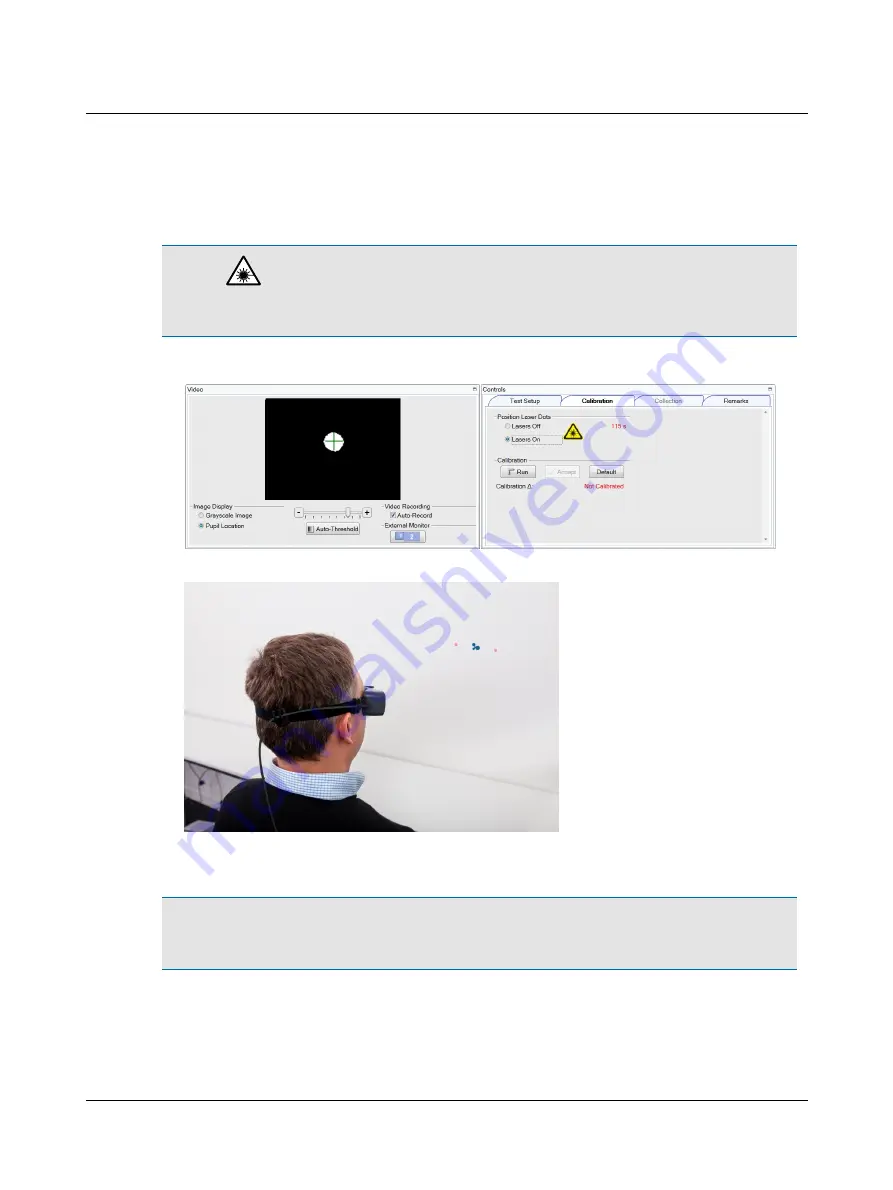
During this procedure both lasers will turn on. Do not look directly at the lasers. Use of controls or

adjustments, or performance of procedures other than those specified herein, may result in hazardous radiation expos-
ure.

1. Click

Lasers On

to turn on both lasers.

2. Ask the patient to position the left and right dots equidistant on each side of the fixation dot.

3. Ask the patient to look at the left dot, then at the right dot. In the

Video

window, check that the cross-hair continues

to track the pupil.

Note

Use the Real Time Traces window to monitor head and eye data. By observing the orange head trace and the

green eye trace, you can tell if the patient is moving their head or eyes (instead of staring at the fixation dot), blinking
excessively, or not following instructions being given (not cooperating).

4. If the cross-hair fails to track the pupil (jumps around and does not stay centered on the pupil), use the + or – button

of the threshold slider to adjust.

Otometrics - ICS Impulse USB

25

8 Oculomotor

Summary of Contents for ICS Impulse USB

Page 1: ...ICS Impulse USB User Guide Doc No 7 50 2060 EN 01 Part No 7 50 20600 EN ...

Page 2: ...latest productinformation available atthe time of publication GN Otometrics A Sreserves the right tomake changes atany time without notice Registeredtrademarks andTrademarks MADSEN IteraII MADSEN OTOflex 100 OTOsuite AURICAL FreeFit AURICAL Visible Speech MADSEN Astera MADSEN Xeta ICS Chartr 200 VNG ENG ICSChartr EP OTOcam300 MADSEN AccuScreen MADSEN AccuLink ICS AirCal AURICAL Aud AURICAL HIT ICS...

Page 3: ...p 16 8 Oculomotor 22 9 Head Impulse 44 10 Positional 75 11 Video Record Playback 97 12 Reports 103 13 System settings 109 14 Installation and Setup 111 15 Upgrading 120 16 Accessories 121 17 Other references 122 18 Standards 122 19 Manufacturer 124 20 Warningnotes 124 21 Definition of symbols 126 22 Notes on EMC Electromagnetic Compatibility 128 Otometrics ICS Impulse USB 3 User Guide ...

Page 4: ... of eye and head movement The ICS Impulse is operated from the OTOsuite Vestibular software 2 Intended use Users The ICS Impulse System is to be used only by qualified medical personnel with prior knowledge of the medical and scientific facts underlying the procedure Use The ICS Impulse System is used in the assessment of the vestibular ocular reflex VOR and nystagmusby measuring recording display...

Page 5: ...trator user name and password are provided with a new installation of OTOsuite Vestibular DO NOT delete the user name or password from the login screen until at least one new user name with password has been added Ensure that at least one user has administrator privileges For information on how to add new users refer to Set up a new user 109 At the login screen Note The password is case sensitive ...

Page 6: ... name The data collection window and all associated tabs open Additional information about the OTOsuite Vestibular screen report findings and working with patients lists is available in the Reference Manual To access the Reference Manual click Reference Manual the button is located in the lower left corner ofthe screen Presentation remote The presentation remote provides an alternative method for ...

Page 7: ...Ifno patient is open a temporary patient is available The temporary patient allows testing to start without entering patient data The patient is given a unique number based on the date and time the patient record was created yyyym mddhhmmsswhere yyyy year mm month hh hour dd day mm minute and ss second Once data is saved you will be prompted to edit the temporary patient information For informatio...

Page 8: ...own arrow and select the appropriate entry The date of birth format is determined by the computer setup and will display as mm dd yyyy or dd mm yyyy where mm month dd day and yyyy year Only numeric characters are allowed alpha characters can not be used Note The patient s birth date is required to determine the age based normative data to be used for head impulse gains for that patient Click Cance...

Page 9: ...rchable last name first name patient ID Gender DOB and Physician To search start typing in the row between the title and the first patient entry Clear search field by clicking the clear button The tests collected for an existing patient are indicated by a checkmark in the appropriate test column Oculomotor Head impulse Positional Videos Note The unique identifier symbol indicates the user has chos...

Page 10: ...the patient list allow you to open and edit the patient file Click Open or double click to open the patient to view test results Previously collected data for the patient is indicated by a checkmark next to each test type name 10 Otometrics ICS Impulse USB User Guide ...

Page 11: ...y patient information in this form Entriesthat cannot be left blank are marked with an asterisk Note The patient s birth date is required to determine the age based normative data to be used for head impulsegains for that patient Otometrics ICS Impulse USB 11 User Guide ...

Page 12: ... order from ascending order A to Z to des cendingorder Z to A Adding remarks toa selected test For more information about selecting atest refer to Selecting a test 12 For more information about test remarks refer to Entering test remarks 15 With the test selected add remarks in the Remarks column of the Test window or click on the Remarks tab The Remarks window includesediting tools Remarksare vis...

Page 13: ...videos that are not needed in order to save disk drive space After avideo s has been deleted the video data cannot be recovered Depending on the test type there may be only a video of the eye or there may also be a room video If the test includes both an eye video and aroom video it is not possible to delete only the eye video or only the room video Oculomotor and Positionalvideos To delete the vi...

Page 14: ...d click the desired test to select it Click Delete Video Caution Clicking Delete Video will delete all videos associated with that test Ifyou choose to delete the video s for the selected test and click Yes at the prompt s the video data is permanently deleted There is no possibility to retrieve the video data 14 Otometrics ICS Impulse USB 6 Managing test data ...

Page 15: ...nt undo and proceeding in reverse order of undo actions Remarksadded during testing are saved according to the test type and session and can be viewed and edited in the Remarks window ofthe selected test Editingremarks Remarksare visible in both the Test and Remarks windows Remarkscan be edited in the Remarks window ofthe selected test In the Remarks column ofthe Test window text can be added and ...

Page 16: ...ng recommended guidelines regard ing cleaning and maintenance Keep the lens cover on the camera when goggles are not in use Keep the instrument clean and as free of dust as possible Remove dust using a soft cloth Ifrequired clean the goggles housing using adamp cloth moistened with a mild detergent and water solution Do not allow any moisture to get inside the goggles Keep moisture away from the c...

Page 17: ...ace cushion should be replaced for each new patient 1 To remove the face cushion slightly flex the goggles out at the side opposite of the camera side and snap out the face cushion Release the face cushion from the other side 2 Properly dispose of the used face cushion 3 Obtain anew face cushion 4 Align the tab ofthe face cushion with the hole on the camera side ofthe goggles 5 Ensure the face cus...

Page 18: ...gles and the patient sface the goggles may slip Improper goggles fit 1 Before putting the goggles on the patient ensure the goggles have a new unused face cushion Refer to Goggles preparation 16 the mirror is clean Refer to Cleaning and maintenance 16 Note The single use disposable face cushion must be replaced for each new patient Caution Improper cleaning may scratch the mirror surfaces 2 Ifrequ...

Page 19: ...skin above the eye up and repositioning the goggles to hold the skin in place 8 Visually inspect the goggles fit Proper goggles fit 7 4 Vision denied solution and goggles placement 7 4 1 Preparing 1 Do not test in aroom with complete darkness While it may NOT seem intuitive for optimal results some ambient room light is beneficial for obtaining a completely light tight test environment for the pat...

Page 20: ...ir eye movement 7 4 2 Attaching the right eye cup 1 Remove the plastic backing from the back side of the cup 2 Ask the patient to open their eye wide Note It is easiest to position the cup if you and the patient are sitting at the same level instead of standing over the patient 3 Ask the patient to stare straight ahead You want the pupil to be in the center ofthe black window 4 Ifthe patient seyel...

Page 21: ...nt look directly at a light bulb spot light halo gen incandescent 3 With the vision denied cup and patch attached well and the patient unable to detect light proceed with placingthe goggleson the patient 7 4 5 Goggles placement over the vision denied solution Note Before placing the goggles over the vision denied solution make sure the goggles have a new unused face cush ion 1 In the OTOsuite Vest...

Page 22: ...ment can vary but must allow you to position the patient at least one meter from the wall or other solid sur face that can be used as a projection surface This position will be utilized for calibration and for VOR testing For Gaze Gaze and Spontaneous and Skew Deviation testing the patient only needs to be positioned comfortably either sitting or in a supine position with the head at a 30 angle Fo...

Page 23: ...sion denied solutionand goggles placement 19 for placement instruc tions 1 Select the test Gaze VOR or Skew Deviation 2 Select the test type For example there are two test types for the Gaze test Gaze and Spontaneous 3 Select the test manuever For example there are five maneuvers for the Gaze test Left Right Up Down and Center A 4 Ifusing the vision denied solution select the check box Vision Deni...

Page 24: ...ye video is always recorded in grayscale 8 Ifthe pupil was not automatically detected select Auto Threshold The system centers the cross hair on the pupil 9 Ask the patient to stare at the fixation dot Assess pupil trackingby observing the cross hair Ifthe cross hair fails to track the pupil jumps around and does not stay centered on the pupil use the or button of the threshold slider to adjust Pu...

Page 25: ...ook at the left dot then at the right dot In the Video window check that the cross hair continues to track the pupil Note Use the Real Time Traces window to monitor head and eye data By observing the orange head trace and the green eye trace you can tell ifthe patient is moving their head or eyes instead of staring at the fixation dot blinking excessively or not following instructions being given ...

Page 26: ...ht equates to the number ofpixels for a15 degree movement of the eye These values are used to analyze eye movement during the impulse testing For more inform ation refer to the Reference Manual appendix that describeshow the calibration values are determined 5 Click Run 6 Ask the patient to face the fixation dot and hold their head still 7 Ask the patient to follow the laser beam dot Note The cali...

Page 27: ...nd head velocities match Examplesof poor calibration show a calibration performed in Head Impulse Poor calibration Eye velocity is too low Poor calibration Eye velocity is too high Otometrics ICS Impulse USB 27 8 Oculomotor ...

Page 28: ...ndow opens and the software is ready to begin collecting head impulse data Caution Once calibration has been performed it is recommended not to reposition the goggles on the patient s head 8 5 Optimizing collection This application provides these features to ensure good data collection External Monitor You have the option to display a larger image of the eye on an external monitor Ifan external mo...

Page 29: ...ded for aminimum of 10 seconds with the eyes positioned at 30 from center right and left as well as 25 from center for up and down In order to assess for alternating or direction changing nystagmusthe eyes should be recorded for more than 2 minutes Please be aware that having the patient look further than the degreesstated above can result in end point nystagmuswhich is not diagnostically relevant...

Page 30: ...uct the patient For example tell them to keep the eyes open and stare toward the left at your finger 3 To begin data collection click Start or click the left button on the presentation remote Horizontal HR and vertical VR eye position traces display in the Eye Position Traces window The default dis play is set in Test Options The real time SPV slow phase velocity value is an estimated value calcul...

Page 31: ...on remote Data will be saved To stop the test early without saving data click Cancel The maximum test duration is set in Test Options The data is analyzed and displayed in the Analysis window 8 8 Gaze data analysis To view a specific test click on the Test window tab and then click the desired test to highlight it For more information about selecting the test refer to Selecting a test 12 Analysiso...

Page 32: ...s refer to Reanalysis 34 Slow Phase Velocity graph The purpose of this graph is to provide a record of the strength ofthe nystagmus This graph displays the individual nys tagmus beats identified by the SPV algorithm for the horizontal right HR and vertical right VR traces The SPV peak is indicated in the graph by a square To select a particular beat click on it or use the left right arrow keys to ...

Page 33: ...n of the test Begin Time time at which analysis began Beat SPV the slow phase velocity for the selected beat Peak SPV where the slow phase velocity peak is set For more information refer to the Reference Manual appendix that describes how the SPV peak is determined Remarks Remarksregarding the test can be entered before during and after testing To add or modify remarks click the Remarks window tab...

Page 34: ... or VR Delete Beat excludes the beat from the analysis and on the report Restore Beats restores all beats that were manually deleted Select Peak click abeat and then select peak A new peak will be set For more information refer to the Refer ence Manual appendix that describes how the SPV peak is determined Restore Peak restores the peak to the location determined by the algorithm 8 8 3 Playback of...

Page 35: ...s the vestibulo ocular reflex VOR with visual enhancement and without visual enhancement The purpose of these two test types is to identify if catch up saccades are present in either test condition The patient is in a sitting position 1 meter from the wall where the fixation target is fixed and the suppression target is pro jected VVOR Visual VOR This test type assessesthe patient svestibulo ocula...

Page 36: ... be displayed Due to the faster frame rate acquisition ofthe camera the Head PositionFeedback is not viewable for VOR tests 2 Instruct the patient For example tell them to keep their eyes open and stare at the fixation dot 3 To begin data collection click Start or click the left button on the presentation remote Trace recordings display in the Real Time Traces window This display includes the eye ...

Page 37: ...on remote Data will be saved To stop the test early without saving data click Cancel The maximum test duration is set in Test Options The data is analyzed and displayed in the Analysis window 8 11 VOR data analysis To view a specific test click on the Test window tab and then click the desired test to highlight it For more information about selecting the test refer to Selecting a test 12 Analysiso...

Page 38: ...st for which data has been collected Operator the person who was logged into OTOSuite Vestibular software when the data was collected Calibration the distance in pixels between the right and left eye positions measured during calibration Test Time date and time data collection was started ElapsedTime duration of the test Remarks Remarksregarding the test can be entered before during and after test...

Page 39: ...Osuite Vestibular software processes the eye position data and calculates the degreesof eye deviation The test provides the ability to assess the patient socular alignment using an alternate cover test The purpose of this test is to identify ifocular misalignment occurs as a result of coveringand uncovering the eye The patient is in asitting pos ition The patient s eye movement is recorded with th...

Page 40: ...e average eye position shift to be calculated correctly manually indicate when the eye is covered or uncovered Click the left button on the presentation remote This button toggles between covered and uncovered Or click Cover Uncover With each click the icon for eye covered or the icon for eye uncovered is inserted below the trace Note You can find more information in the ICS Impulse training video...

Page 41: ... the test early without saving data click Cancel The maximum test duration is set in Test Options The data is analyzed and displayed in the Analysis window 8 14 Skew Deviation data analysis To view a specific test click on the Test window tab and then click the desired test to highlight it For more information about selecting the test refer to Selecting a test 12 Analysisof the test results can be...

Page 42: ...ofthe trace seen in the Traces window centered around the cursor 8 14 2 Analysis details Info The test parameters are listed Test Type name of test for which data has been collected Operator the person who was logged into OTOSuite Vestibular software when the data was collected Calibration the distance in pixels between the right and left eye positions measured during calibration Test Time date an...

Page 43: ...elections Play Plays the video Pause Pauses the video Stop Stops the video Play from Cursor Select to start the playback at the position ofthe cursor Ifnot selected play back starts at the beginning ofthe trace Speed Note Before setting the playback speed check the recorded frame rate fps stated below the eye video Normal eye video recorded at 30 frames per second can only be played back at normal...

Page 44: ...ont of the fixation dot 9 2 Pupil detection Refer to Goggles placement 18 for placement instructions 9 2 1 Lateral test Note It is recommended to do the Lateral test prior to doing either the LARP or RALP test Calibration must be with Lateral test type selected 1 Choose the Impulse Type Lateral 2 For patients with spontaneous nystagmusor gaze evoked nystagmus evoked by gaze position during head im...

Page 45: ...f173 fps 5 In the Video window choose the type ofimage displayed Grayscale Image A or Pupil Location B Note The choice of Grayscale Image or Pupil Location is only used for setting the pupil detection Eye video is always recorded in grayscale 6 Ifthe pupil was not automatically detected select Auto Threshold The system centers the cross hair on the pupil 7 Ask the patient to stare at the fixation ...

Page 46: ... e head trace should be bold in the Real Time Trace It also determines the shape ofthe training curves 2 For patients with spontaneous nystagmusor gaze evoked nystagmus evoked by gaze position during head impulse select the check box Spontaneous Nystagmus By selecting this check box for a patient who has spontaneous nys tagmus or gaze evoked nystagmus it prevents good impulses from being rejected ...

Page 47: ...ion the ROI Region of Interest around the pupil click on the green box and drag to center it on the pupil or click on the pupil to center the pupil inside the green box 6 Ask the patient to stare at the fixation dot Assess pupil trackingby observing the cross hair Ifthe cross hair fails to track the pupil jumps around and does not stay centered on the pupil move the threshold slider to adjust 7 Se...

Page 48: ...t the left dot then at the right dot In the Video window check that the cross hair continues to track the pupil Note Use the Real Time Traces window to monitor incoming data By observing the head trace orange blue pink and the eye trace green you can tell if the patient is moving their head or eyes instead of staring at the fixation dot blinking excessively or not following instructions being give...

Page 49: ...t equates to the number ofpixels for a15 degree movement of the eye These values are used to analyze eye movement during the impulse testing For more inform ation refer to the Reference Manual appendix that describeshow the calibration values are determined 5 Click Run 6 Ask the patient to face the fixation dot and hold their head still 7 Ask the patient to follow the laser beam dot Note The calib...

Page 50: ...ies match Poor calibration Eye velocity is too low Poor calibration Eye velocity is too high 3 Ifthe eye and head velocities do not match you need to recalibrate or review the patient s history 50 Otometrics ICS Impulse USB 9 Head Impulse ...

Page 51: ...n Data NOT within normal limits could be related to a peripheral and or central disorder Use the VOR tests to assess a patient with catch up saccades during calibration check 4 Once the calibration has been checked and you are satisfied with the result click Accept The Collection window opens and the software is ready to begin collecting head impulse data Caution Once calibration has been performe...

Page 52: ... a surface in front ofthem the tester rotates the patient s head hori zontally for a lateral head impulse test through a small angle about 10 20 degrees in a brief abrupt and unpredictable manner varying the direction and the velocity For LARP turn the patient s head 35 45 degrees to the right Have the patient stare at the fixation dot The pupil of the right eye will be close to the nose The teste...

Page 53: ...20 Minimum Acceptable Peak Head Velocity 100 s 250 s Peak Head Acceleration 1000 s2 2500 s2 RALP Head Impulse Note You can find more information in the ICS Impulse training video at icsimpulse com or at www headimpulse com The goggles collect both head and eye data The gyroscope measures the velocity ofthe head movement the stimulus The high speed camera capturesthe image of the eye The OTOsuite V...

Page 54: ...ettings A define how many valid left and right impulses are required before the test stops auto matically To change the number ofsuggested minimum head impulses for the current testing session click the up or down arrows or type in the number directly Twenty 20 is the recommended minimum number of head impulses for both leftward and rightward impulses Note Impulse settingscan be any number up to 9...

Page 55: ...led grayed out Start button indicatesthe system is ready for head impulse data collection Otherwise you must click Start or click the left button on the presentation remote to begin head impulse data collection Caution Touching the goggles or the goggles strap while moving the patient s head can result in moving the camera which produces artifactsin the collection data 3 Standingbehind the patient...

Page 56: ...lso the test date and time is displayed Frame Rate frequency of data acquisition in frames per second fps Calibration the distance in pixels between the right and left eye positions measured during calibration A Test Type B ElapsedTime C Frame Rate D Calibration Note To stop the test early click Stop or press the right button on the presentation remote Data will be saved Data is saved ifat least o...

Page 57: ...rate is 250 samples per second Operator feedback is also displayed for the current impulse A green circle indicatesthat the head impulse was accepted performed adequately An orange circle indicates that the head impulse was rejected not performed properly A message displays in the col lection window ifone ofthese errors was the cause Too slow head velocity not fast enough Too much overshoot at the...

Page 58: ...ented in green White dots display along the Y axis to indicate the velocities of impulses collected The collection algorithm analyzes the data in real time as it is being collected Ifthe head impulse meets the algorithm cri teria an accepted head impulse will be counted in the collection window A head impulse that matches the training curve is typically counted as an accepted valid head impulse Co...

Page 59: ...normal mode or enlarged mode refer to the Reference Manual 9 8 Analysis details 9 8 1 Gain Reviewing the eye and head traces is the first step in interpreting the data See 2D Analysis window 64 Reviewing the gain data should always be secondary Gain is the ratio of the eye movement velocity to the head movement velocity Individual gains and the mean gain are dis played The Gain window displays gai...

Page 60: ...rea indicatesunilateral loss Data in the dark gray area indicates bilateral loss To change the normative cutoff values refer to the Reference Manual Age based normative data Age based normative cutoff values are defined as the mean 2 standard deviations for the age range 10 to 99 years On the gain graph an outline definesthe area inside of which the data is considered within normal limits 1 Newman...

Page 61: ...of the eyes Never stand in front of the patient and have them fixate on your nose when using ICS Impulse This method oftesting will result in higher VOR gains 3 During testing the real time trace showed that the eyes were leading the head but the test was allowed to continue Ifthis problem is observed the goggles and patient setup should be checked before continuing the test 4 Ifyou have ruled out...

Page 62: ... arrow keys or the scroll wheel on the mouse to move from trace to trace The highlighted trace is the selected trace E In The corresponding gain point is selected gain value is not displayed A Status bar B Gain window C Gain value D Trace window E Selected trace To delete a selected head impulse Move the cursor over the gain point Double click the mouse Click in the trace window Use the arrow keys...

Page 63: ...Remarks window tab For information about the editing tools refer to the Reference Manual Note Text previously added in the Test window appears in the Remarks window 9 8 4 Display To change the Gain graph display click the Left and or Right check boxes to select deselect what displays both gains left gains only or right gains only To modify the 2D graphs display click the Head Velocity and or Eye V...

Page 64: ...ht Side Refer to the Reference Manual To view only the head or eye velocity click the Display window tab and click the Head Velocity or Eye Velocity check box To view both head and eye velocities select both check boxes Head data is shown in blue for left and orange for right Eye data shown in green identifies eye movement during and after the head impulse VOR Eye data shown in red identifies sacc...

Page 65: ...at the Gain graph the data points are all within the normal range in the white area The head data shows very well performed head impulsesand the eye data shows avestibular ocular reflex A that mirrors the head velocities There may be a few catch up saccades Otometrics ICS Impulse USB 65 9 Head Impulse ...

Page 66: ... Gain graph the data points are all within the gray range indicating a unilateral loss The head data shows very well performed head impulses and the eye data shows an inadequate vestibular ocular reflex A that does not mirror the head velocities There are overt catch up saccades present B Catch up saccades are easier to visualize in the 3D analysis 66 Otometrics ICS Impulse USB 9 Head Impulse ...

Page 67: ...ndow The Hex Plot window provides an overview of the mean gains as well as the 2D analysis graphs for all selected tests The tests initially selected are the same as the tests selected in the 2D and 3D Analysis windows Mean gains are represented by bars that vary in length according to the mean gain value The bars are displayed inside a hexagon Each side of the hexagon is labeled with a two letter...

Page 68: ...ext to the test name in the Show column Only one test for each test type may be selected to display on the hex plot Note The test selections revert back to the test selections in the 2D and 3D Analysis windows when the Hex Plot win dow is no longer displayed A The method for calculating relative right left vestibulo ocular reflex asymmetry the Asymmetry values is as fol lows 1 x Asymmetry 1 100 lo...

Page 69: ... the right graph right head and eye velocity data on the right and the left graph left head and eye velocity data on the left To switch the layout click the Head Impulse window tab in the Options window and select Display Left Graph on Right Side Refer to the Reference Manual The data can be viewed from 360 degrees To see the data from different views hold down left mouse button and rotate as desi...

Page 70: ...Gain graph the data points are all within the normal range in the white area The head data shows very well performed head impulsesand the eye data shows avestibular ocular reflex A that mirrors the head velocities There may be a few catch up saccades 70 Otometrics ICS Impulse USB 9 Head Impulse ...

Page 71: ... graph the data points are all within the gray range indicating a unilateral loss The head data shows very well performed head impulses and the eye data shows an inadequate vestibular ocular reflex A that does not mirror the head velocities There are overt catch up saccades present B On the right side the downward spikes are due to spontaneous nystagmus Otometrics ICS Impulse USB 71 9 Head Impulse...

Page 72: ...loss Note the asymmetry of 56 The right abnormal side is affecting the left normal side The head data shows well performed head impulses and the eye data shows an inadequate vestibular ocular reflex A that does not mir ror the head velocities There are covert catch up saccades present B Notice how the covert catch up saccadesare closer to the head data whereas the overt catch up saccadeswere furth...

Page 73: ...ion has occurred Ifthere are three or more tests available the three that display initially are the first test the most recent test and the test currently displayed in 2D and 3D window To remove a test from the display click the button next to the test name in the Show column To add a test s to the display click the button next to each test name in the Show column Note The viewing mode functions t...

Page 74: ... are color blind to easily distinguish the different colors To change the colors used for each type ofdata click the Graph Colors window tab in the Options window Refer to the Reference Manual The default layout places the right graph right head and eye velocity data on the right and the left graph left head and eye velocity data on the left To switch the layout click the Head Impulse window tab i...

Page 75: ...ilized for calibration For Dynamic and Repositioning testingthe patient needs to be comfortably positioned on an exam table as they will be moving between a sittingand a supine position For Calibration Purposes Note The patient should be seated in a chair that is stationary and does not swivel 1 Choose awall that allows you to position the patient at least one meter in front ofthe fixation dot 2 A...

Page 76: ...es placement 19 for placement instruc tions 1 Select the test Dynamic or Repositioning 2 Select the test type For example there are three test types for the Dynamic test Dix Hallpike Hallpike Stenger and Roll 3 Select the test condition For example there are four conditions for the Dix Hallpike test Head Left Head Right Head Left Repeat and Head Right Repeat 4 Ifusing the vision denied solution se...

Page 77: ...ye video is always recorded in grayscale 8 Ifthe pupil was not automatically detected select Auto Threshold The system centers the cross hair on the pupil 9 Ask the patient to stare at the fixation dot Assess pupil trackingby observing the cross hair Ifthe cross hair fails to track the pupil jumps around and does not stay centered on the pupil use the or button of the threshold slider to adjust Pu...

Page 78: ...ook at the left dot then at the right dot In the Video window check that the cross hair continues to track the pupil Note Use the Real Time Traces window to monitor head and eye data By observing the orange head trace and the green eye trace you can tell ifthe patient is moving their head or eyes instead of staring at the fixation dot blinking excessively or not following instructions being given ...

Page 79: ...ht equates to the number ofpixels for a15 degree movement of the eye These values are used to analyze eye movement during the impulse testing For more inform ation refer to the Reference Manual appendix that describeshow the calibration values are determined 5 Click Run 6 Ask the patient to face the fixation dot and hold their head still 7 Ask the patient to follow the laser beam dot Note The cali...

Page 80: ...n show a calibration performed in Head Impulse Poor calibration Eye velocity is too low Poor calibration Eye velocity is too high 3 Ifthe eye and head velocities do not match you need to recalibrate or review the patient s history 80 Otometrics ICS Impulse USB 10 Positional ...

Page 81: ...s and the software is ready to begin collecting head impulse data Caution Once calibration has been performed it is recommended not to reposition the goggles on the patient s head 10 5 Optimizing collection and treatment This application provides these features to ensure good data collection and well performed treatment maneuvers External Monitor You have the option to display a larger image of th...

Page 82: ...ntation with respect to gravity The patient typically begins in asitting position and is moved into a position which will align either the anterior posterior or the lateral canals perpendicular to the floor and the canal s thus affected by gravity These tests are used to determine if apatient s symptoms are caused by benign paroxysmal positional vertigo Dix Hallpike or Hallpike Stenger This test a...

Page 83: ...testing to start without entering any patient data Refer to Patient data entry lists 7 to create a new patient or open an existing patient When collecting data you can monitor head movement using the Head PositionFeedback display ensures that the head is properly positioned during the entire test or maneuver or Synchronized Room Video You can also choose to not use either The default display is se...

Page 84: ...r right area of the window Green When the variability is low there is ahigh probability that the value is reliable Orange When the variability is high there is less probability that the value is reliable Note SPV values displayed in orange should be considered less reliable but not inaccurate The real time SPV allows the tester to easily monitor the presence or absence of nystagmus The tester will...

Page 85: ... remote Data will be saved To stop the test early without saving data click Cancel The maximum test duration is set in Test Options The data is analyzed and displayed in the Analysis window 10 8 Dynamic data analysis To view a specific test click on the Test window tab and then click the desired test to highlight it For more information about selecting the test refer to Selecting a test 12 Analysi...

Page 86: ...e purpose of this graph is to provide a record of the strength ofthe nystagmus This graph displays the individual nys tagmus beats identified by the SPV algorithm for the horizontal right HR and vertical right VR traces The SPV peak is indicated in the graph by a square To select a particular beat click on it or use the left right arrow keys to move between beats The SPV value for the beat is disp...

Page 87: ...n of the test Begin Time time at which analysis began Beat SPV the slow phase velocity for the selected beat Peak SPV where the slow phase velocity peak is set For more information refer to the Reference Manual appendix that describes how the SPV peak is determined Remarks Remarksregarding the test can be entered before during and after testing To add or modify remarks click the Remarks window tab...

Page 88: ...or VR Delete Beat excludes the beat from the analysis and on the report Restore Beats restores all beats that were manually deleted Select Peak click abeat and then select peak A new peak will be set For more information refer to the Refer ence Manual appendix that describes how the SPV peak is determined Restore Peak restores the peak to the location determined by the algorithm 10 8 3 Playback of...

Page 89: ...hange the patient s body orientation with respect to gravity CRT and liberatory maneuvers begin with the patient in the sitting position The BBQ roll maneuver begins with the patient in the supine position with the head elevated 30 Then the patient is rotated so that the particles are moved out ofthe affected canal Note The Head Position Feedback ensures that the head is properly positioned during...

Page 90: ...able to allow testing to start without entering any patient data Refer to Patient data entry lists 7 to create a new patient or open an existing patient When collecting data you can monitor head movement using the Head PositionFeedback display ensures that the head is properly positioned during the entire test or maneuver or Synchronized Room Video You can also choose to not use either The default...

Page 91: ...r right area of the window Green When the variability is low there is ahigh probability that the value is reliable Orange When the variability is high there is less probability that the value is reliable Note SPV values displayed in orange should be considered less reliable but not inaccurate The real time SPV allows the tester to easily monitor the presence or absence of nystagmus The tester will...

Page 92: ...ote Data will be saved To stop the test early without saving data click Cancel The maximum test duration is set in Test Options The data is analyzed and displayed in the Analysis window 10 11 Repositioning data analysis To view a specific test click on the Test window tab and then click the desired test to highlight it For more information about selecting the test refer to Selecting a test 12 Anal...

Page 93: ...s refer to Reanalysis 95 Slow Phase Velocity graph The purpose of this graph is to provide a record of the strength ofthe nystagmus This graph displays the individual nys tagmus beats identified by the SPV algorithm for the horizontal right HR and vertical right VR traces The SPV peak is indicated in the graph by a square To select a particular beat click on it or use the left right arrow keys to ...

Page 94: ...on of the test Begin Time time at which analysis began Beat SPV the slow phase velocity for the selected beat Peak SPV where the slow phase velocity peak is set For more information refer to the Reference Manual appendix that describes how the SPV peak is determined Remarks Remarksregarding the test can be entered before during and after testing To add or modify remarks click the Remarks window ta...

Page 95: ...or VR Delete Beat excludes the beat from the analysis and on the report Restore Beats restores all beats that were manually deleted Select Peak click abeat and then select peak A new peak will be set For more information refer to the Refer ence Manual appendix that describes how the SPV peak is determined Restore Peak restores the peak to the location determined by the algorithm 10 11 3 Playback o...

Page 96: ... setting the playback speed check the recorded frame rate fps stated below the eye video Normal eye video recorded at 30 frames per second can only be played back at normal speed Slow eye video recorded at 60 frames per second can be played back at normal or slow speed Slower eye video recorded at 60 frames per second can be played back at normal slow or slower speed 96 Otometrics ICS Impulse USB ...

Page 97: ...11 Video Record Playback Record When recording an eye video there are 2 image size options Full Image or Region of Interest ROI Full Image Otometrics ICS Impulse USB 97 11 Video Record Playback ...

Page 98: ...ls refer to the Reference Manual Video Record buttons and selections Start Start video recording Stop Stop video recording Note There is no limit to the length ofthe video recording however the longer the video recording is the larger the file will be on the hard drive 98 Otometrics ICS Impulse USB 11 Video Record Playback ...

Page 99: ...rea inside the ROI box Vision Denied select to indicate the recording was done with vision denied Eye Record Speed Options for recording Full Image 30 fps 60 fps Options for recording ROI 30 fps 60 fps 120 fps Compress eye video select to reduce video file size Note Ifthe video is recorded at 60 or 120 frames per second it can be played back in slow motion or at normal speed At normal speed some f...

Page 100: ...ile size External Monitor To display the eye video on the computer monitor as well as on an external monitor click You can record eye video only or eye video with room video Ifyou chose to combine eye and room video this example shows the resulting file size for a 20 minute recording Eye Video 60 fps compressed Room Video 15 fps grayscale Eye Video Eye Video Size Room Video Size Combined Video Fil...

Page 101: ...rk a file for aspecific purpose for example to indicate abnormal results click in the check box under the column heading marked with this unique identifier File Size MB File size of the eye video Ifthe synchronized room video was used during recording the file size is a combination of the eye and room video Recording information is listed with the video Date and time the video was recorded The cur...

Page 102: ...ata cannot be recovered Playback Speed Note Before setting the playback speed check the recorded frame rate fps stated below the eye video Normal eye video recorded at 30 frames per second can only be played back at normal speed Slow eye video recorded at 60 frames per second can be played back at normal or slow speed Slower eye video recorded at 120 frames per second can be played back at normal ...

Page 103: ... using vector based graphics Vector based graphicsprovide exceptional print quality and are journal quality for publication submissions The default report is automatically saved To make changes to the current report refer to Edit Report 104 and Review Report Options 106 Note Changes can be made that apply to all reports such as which patient data and facility data are included or that apply only t...

Page 104: ...e history Selected items are added to the report section titled Symptoms Impressions From this list select overall medical impression s based on the test results Selected items are added to the report section titled Impressions Macros For each test performed select overall finding s from this list to insert in the text field A Text seen in the text field is added to the report section titled Findi...

Page 105: ...click each check box that applies From the Macros list click the name ofthe macro and click Insert Note Some macros have text longer than what can be displayed in the list window To see the entire text roll the cursor over the macro name Otometrics ICS Impulse USB 105 12 Reports ...

Page 106: ...ab and click the check box at the left ofthe test name in the Include Res ults From list Clicking the check box again removesthe test from the report The Include Results From list is divided into 3 test groups Oculomotor Head Impulse and Positional Tests are listed with the test date and time and test name The name is the test type and test direction Depending on the test and what settings and rem...

Page 107: ...atient file Head Impulse Test Options Includes Calibration Graph asnapshot of the real time eye and head trace during the calibration check Gain Graph gain graph displayed in the 2D 3D window Mean Gains mean gain symbols on the gain graph as displayed in the 2D 3D window values display by default mean gain symbols and values on the gain graphs displayed in the progress data win dow Age Normative D...

Page 108: ...ation phase or centered around the cursor when the cursor has been moved to a new position in the analysis window Vertical Traces a30 second recording ofthe vertical eye position trace centered around the cul mination phase or centered around the cursor when the cursor has been moved to a new position in the analysis window Peak SPV the degrees per second of the slow phase velocity peak as set in ...

Page 109: ... locations are set for shared files videos reports PDF export and import For more information refer to Changing the storage locations for videos export import report PDFs 118 for more information List operations The user data is separated into columns according to the type of information Last name first name user name etc Set up a new user Important Set up at least one user with administrator priv...

Page 110: ...firmware 4 Click Save to save the changes Click Cancel to discard the changes Edit user data 1 Select the user from the list 2 Click Edit 3 Edit the changes making sure all required fields marked with an asterisk are completed 4 Click Save to save the changes Click Cancel to discard the changes Delete user 1 Select the user from the list 2 Click Delete 3 Click OK Additionalsystem settings Workstat...

Page 111: ...e Reader Settingup a networked database and workstation not required for standalone installations 14 1 Minimum computer requirements Operating System 64 bit Windows 8 Pro Windows 7 Professional 32 bit Windows 8 Pro Windows 7 Professional CPU Intel i5 processor Memory 64 bit Windows 8 or Windows 7 6 GB 32 bit Windows 8 Windows7 4 GB Disk Space 300 GB Connectors One USB 2 0 for the goggles and up to...

Page 112: ...e For Windows 7 and Windows 8 systems a message that refers to the User Account Control UAC may display Accept this message as it does not indicate a problem Microsoft Webcam or SQL Server error messages If Microsoft has installed new Window updates and the com puter has not been rebooted an error message may appear Please reboot your PC and restart the software install ation 1 Save any files curr...

Page 113: ... the database for one or more client workstations where the OTOsuite Vestibular application is installed We recommend client server installsto be set up using network domains Use of workgroups is not recommended because it will require the same user name and password be used on each computer In standalone a single computer hosts both the database and the OTOsuite Vestibular applications Choose how...

Page 114: ...ck Next and continue at Complete the installation 114 4 IfServer was selected click Next and continue at Complete the installation 114 Client installation 1 Select Client and click Next 2 Enter the port number and the server computer name obtained from the server installation 3 Click Next and continue at Complete the installation 114 Complete the installation 1 Click Install A status window appear...

Page 115: ... The current version of goggles has a single USB cable that connects dir ectly to the computer 1 Remove the cover from the lens of the goggles Note Keep the cover When the goggles are not in use put the cover back on to prevent dust from accumulating on the lens 2 Connect the USB cable to the 2 0 USB connector on the computer Note Installing the driver for the goggles takes a few minutes The messa...

Page 116: ...B 4 Double click the LifeCam executable file exe and follow the instructions Note Possibleerror messagesand what to do if they appear Microsoft Webcam or SQL Server error messages If Microsoft has installed new Window updates and the computer has not been rebooted an error message may appear Please reboot your PC and restart the softwareinstallation 5 When the synchronized room video installation ...

Page 117: ...an be imported giving you the ability to view patient data and analysis for various diagnoses 1 Ifthe Patients window is not open click Patient List 2 Click Import 3 Click Open Folder The Import folder is highlighted 4 Below the Import folder click the Demodata folder and click OK 5 Select all patient files that appear in the Patient Import window 6 Click Import 7 Click OK Note Ifyou are upgrading...

Page 118: ...n or paper size Refer to the Reference Manual 14 9 Installing Adobe Reader For access to the digital version of the Reference Manual Adobe Reader must be installed on the computer Install the copy provided on the OTOsuite Vestibular DVD ifrequired 1 Browse the DVD to locate the Adobe Reader file 2 Double click Adobe Reader to start the installation and follow the on screen instructions 3 The insta...

Page 119: ...ion for the folder displays in the OTOsuite Vestibular Storage Locations window Note For each location that has been changed new files will be stored at the new location For example if the loc ation has been changed for video files new video recordings will be stored at the new location For each new location existing files should be moved from the previous location to the new location Otometrics I...

Page 120: ...ess 1 Save any files currently open and quit all programs 2 Insert the DVD received with the upgrade of OTOsuite Vestibular application Note Ifthe computer is set up to AutoRun the installation starts If AutoRun is not initialized browse the DVD to find this icon 3 Click setup You may need to close the DVD content folder 4 Click Yes to the question in the security dialog 5 The Welcome screen appea...

Page 121: ...D vHIT Training Video DVD Positional Training Video DVD 8 49 82700 8 49 82703 8 49 82701 8 49 82702 Software OTOsuite Vestibular 8 49 92400 Goggles Face cushion 120 pkg 8 62 50200 Strap assembly 8 35 34200 Optical cleaning cloth Qty min 3 7590527 Fixation dot 2 sheets pkg 1 26 44000 Vision Denied Solution 200 sets pkg 8 62 50700 Remote Control Clip 8 36 00600 Synchronized Room Video Microsoft Life...

Page 122: ...ingRate 250 fps Impulse VOR Video Record Playback 173 fps Gaze Skew Deviation Dynamic Repositioning Video Recording 30 60 or 120 Hz Impulse Gaze VOR Skew Deviation Dynamic Repositioning Video Record Playback Eye Tracking 100 x 100 pixels Impulse VOR 160 x 120 pixels Gaze Skew Deviation Dynamic Repositioning Software WindowsGraphical User Interface High Performance Analysis Software Database Storag...

Page 123: ...Environment Temperature 15 C to 29 C 59 F to 84 2 F Rel Humidity 30 to 90 non condensing Air Pressure 700 hPa to 1060 hPa Operations at temperatures below 20 C 4 F or above 60 C 140 F may cause permanent damage to the device Storingand Handling Temperature 20 C to 60 C 4 F to 140 F Rel Humidity 90 non condensing Air Pressure 500 hPa to 1060 hPa Standards Safety Complieswith UL 60601 1 1 ed IEC 606...

Page 124: ...are not designed to be used in conjunction with any devices not approved by GN Otometrics Summation of combined unapproved parts could result in increased electrical leakage All parts ofthe ICS Impulse system are suitable for use within the patient environment When the ICS Impulse System is used in conjunction with a test device make sure that all information cautions and warn ings in the manual f...

Page 125: ...fields 12 No defibrillators or high frequency surgical equipment should be applied to the patient when connected to the ICS Impulse System at any time 13 Immediately discontinue use ofthe equipment ifskin irritation or discomfort occurs 14 Installation ofany third party software applications programs or utilities other than those specified by GN Oto metricscan compromise the safety or effectivenes...

Page 126: ... same safety requirements as the ICS Impulse system may lead to a reduction in the overall safety level ofthe system The ICS Impulse system is designed to ensure com pliance with requirements in EN 60601 1 or IEC 60601 1 2005 3 ed when the PC printer etc are placed out of reach ofthe patient i e not closer than approx 1 5 meters 5 ft 21 Definition of symbols ICS Impulse Sys tem CAUTION Laser radia...

Page 127: ... municipal waste You can return your device and accessories to Otometrics or to any Oto metricssupplier You can also contact your local authorities for advice on dis posal Complieswith Medical Devices Directive 93 42 EEC and RoHS Directive 2011 65 EC Suitable for direct current only Appliesto the goggles Complieswith Class II requirements ofthe safety standard IEC 60601 1 21 1 Label locations For ...

Page 128: ...d in such anenvironment Emissionstest Compliance Electromagneticenvironment guidance RF emissions CISPR 11 Group 1 ICS Impulse USB uses RF energy only for its internal function Therefore its RF emissionsare very low and are not likely to cause any inter ference in nearby electronic equipment RF emissions CISPR 11 Class A ICS Impulse USB is suitable for use in all establishments other than domestic...

Reviews: