


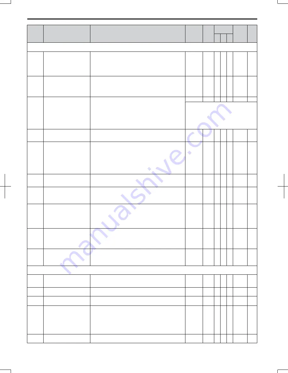
No.
Name
Description
Range
Def.
Control
Mode
Addr.
Hex
Pg.
V/f O
LV
P
M
b1: Operation Mode Selection
Use b1 parameters to configure the operation mode.
b1-01 Frequency Reference
Selection 1
Selects the frequency reference input source.
0: Operator - Digital preset speed d1-01 to d1-17.
1: Terminals - Analog input terminal A1 or A2.
2: MEMOBUS communications
3: Option PCB
4: Pulse Input (Terminal RP)
0 to 4
1
S S S
180
102
b1-02 Run Command Selection 1
Selects the run command input source.
0: Operator - RUN and STOP keys on the digital operator.
1: Digital input terminals
2: MEMOBUS communications
3: Option PCB.
0 to 3
1
S S S
181
104
b1-03 Stopping Method Selection
Selects the stopping method when the run command is
removed.
0: Ramp to Stop
1: Coast to Stop
2: DC Injection Braking to Stop
3: Coast with Timer (A new run command is ignored if
received before the timer expires)
9: Simple Positioning
0 to 3, 9
0
S S S
182
105
DC Injection Braking at Stop cannot be
selected when using Open Loop Vector for
PM motors.
b1-04 Reverse Operation Selection
Permits or prohibits reverse operation.
0: Reverse enabled.
1: Reverse disabled.
0,1
0
A A A
183
107
b1-07 LOCAL/REMOTE Run
Selection
Determines the operation when the Run command source is
switched from LOCAL to REMOTE or between Run source
1 and 2 while an external Run command is active at the new
source.
0: External Run command has to be cycled at the new source
to be activated.
1: External Run command at new source is accepted
immediately.
0,1
0
A A A
186
107
b1-08 Run Command Selection
while in Programming Mode
0: Run command accepted only in the operation menu.
1: Run command accepted in all menus.
2: Prohibit entering Programming Mode during Run
0 to 2
0
A A A
187
108
b1-14 Phase Order Selection
Sets the phase order for drive output terminals U/T1, V/T2
and W/T3.
0 : Standard
1 : Switch phase order
0,1
0
A A A
1C3
108
b1-15 Frequency Reference 2
Selects the frequency reference input source.
0: Operator - Digital preset speed d1-01 to d1-17.
1: Terminals - Analog input terminal A1 or A2
2: MEMOBUS communications
3: Option PCB
4: Pulse Input (Terminal RP)
0 to 4
0
A A A
1C4
108
b1-16 Run Command Source 2
Selects the run command input source.
0: Operator - RUN and STOP keys on the digital operator.
1: Digital input terminals
2: MEMOBUS communications
3: Option PCB
0 to 3
0
A A A
1C5
108
b1-17 Run Command at Power Up
Determines the operation when a Run command is active at
power up of the drive.
0: Run command not issued, needs to be cycled
1: Run command issued, motor operation start
0,1
0
A A A
1C6
108
b2: DC Injection Braking
Use b2 parameters to configure DC Injection Braking operation
b2-01
DC Injection Braking Start
Frequency
Sets the frequency at which DC Injection Braking starts when
Ramp to Stop (b1-03 = 0) is selected. If b2-01< E1-09, DC
Injection Braking starts at E1-09.
0.0 to 10.0 0.5
Hz
A A A
189
109
b2-02
DC Injection Braking
Current
Sets the DC Injection Braking current as a percentage of the
drive rated current.
0 to 75
50% A A −
18A
109
b2-03
DC Injection Braking Time/
DC Excitation Time at Start
Sets DC Injection Braking time at start. Disabled when set to
0.00 seconds.
0.00 to
10.00
0.00 s
<1>
A A −
18B
109
b2-04
DC Injection Braking Time at
Stop
Sets DC Injection Braking time at stop.
When b1-03 = 2, actual DC Injection time is calculated as
follows:
(b2-04) x 10 x (Output Freq)/(E1-04). When b1-03 = 0, this
parameter sets the amount of DC Injection time applied to the
motor at the end of the decel ramp or High Slip Braking.
Disabled when set to 0.00.
0.00 to
10.00
0.50 s A A −
18C
110
b2-08
Magnetic Flux
Compensation Value
Sets the magnetic flux compensation as a percentage of the
no-load current value (E2-03).
0 to 1000
0%
− A −
190
110
B.2 Parameter Table
300
SIEP C710606 20 OYMC AC Drive - V1000 User Manual
7/16/2008-13:23


