29
3-3
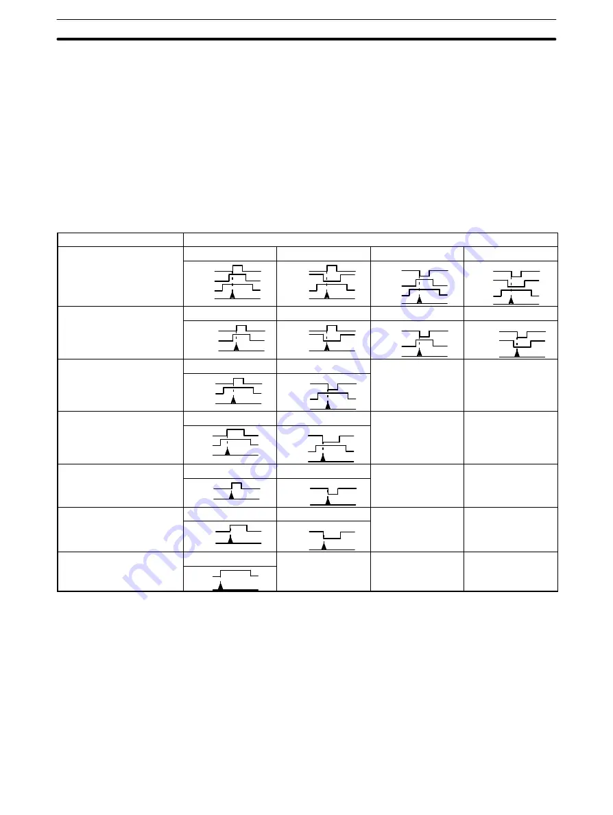
Counter Reset Conditions
Counter reset conditions vary according to the combination of inputs used and
pin settings on the back panel DIP switch. The DIP switch settings required for
the input combinations shown in the following table and the operating modes
that can be used with each are shown on the next page. (The numbers 1 through
17 above the input patterns correspond to the settings.) Resetting is not possible
in the gate, latch, and sampling operating modes. All inputs for each pattern
must be in the status shown for setting to be effective. The minimum input pulse
width for the input Z is 0.1 ms;that for the control input IN1, 1 ms.
In the following table, input Z is indicated by Z; control input IN1, by IN1, and the
internal reset bit, by IRB. The point at which the reset actually takes place is indi-
cated by the arrow at the bottom of each pattern. The DIP switch settings for
each pattern are described on the following page.
Inputs used
Reset conditions and timings
1
2
3
4
Input Z
Control input IN1
Internal reset bit
Z
IN1
IRB
Z
IN1
IRB
Z
IN1
IRB
Z
IN1
IRB
5
6
7
8
Input Z
Control input IN1
Z
IN1
Z
IN1
Z
IN1
Z
IN1
9
10
Input Z
Internal reset bit
Z
IRB
Z
IRB
11
12
Control input IN1
Internal reset bit
IN1
IRB
IN1
IRB
13
14
Input Z
Z
Z
15
16
Control input IN1
IN1
IN1
17
Internal reset bit
IRB
Counter Reset Conditions
Section 3-3
Summary of Contents for SYSMAC C200H-CT001-V1
Page 1: ...Cat No W141 E1 4 High speed Counter Units SYSMAC C200H CT001 V1 CT002 OPERATION MANUAL...
Page 2: ......
Page 3: ...C200H CT001 V1 CT002 High speed Counter Units Operation Manual Revised September 2000...
Page 4: ...iv...
Page 6: ...vi...
Page 8: ......
Page 10: ......
Page 20: ......
Page 46: ......
Page 96: ......
Page 98: ......


