10
2-2
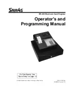
Wiring
Names of inputs and outputs and the pin arrangement of the connector are
shown below (as viewed from the front). The connector is a Fujitsu
FCN-361J040 (solder type), and is included with the Counter Unit.
Row B
Pin no.
Row A
Input A: 24 VDC
20
Input A: 12 VDC
Input A: 0 V
19
Input A: 5 VDC
Input B: 24 VDC
18
Input B: 12 VDC
Input B: 0 V
17
Input B: 5 VDC
Input Z: 24 VDC
16
Input Z: 12 VDC
Input Z: 0 V
15
Input Z: 5 VDC
14
13
Control input IN1: 12/24 VDC
Control input IN1: 0 V
12
Control input IN1: 5 VDC
11
Control input IN2: 12/24 VDC
Control input IN2: 0 V
10
Control input IN2: 5 VDC
9
Outputs 0 through 3
Power supply: 5 to 24 VDC
8
Output 0
7
Output 1
Outputs 0 through 3, COM: 0 V
6
Output 2
5
Output 3
Outputs 4 through 7
Power supply: 5 to 24 VDC
4
Output 4
3
Output 5
Outputs 4 through 7, COM: 0 V
2
Output 6
1
Output 7
Connector Pin Arrangement
C200H-CT001-V1
Wiring
Section 2-2
Summary of Contents for SYSMAC C200H-CT001-V1
Page 1: ...Cat No W141 E1 4 High speed Counter Units SYSMAC C200H CT001 V1 CT002 OPERATION MANUAL...
Page 2: ......
Page 3: ...C200H CT001 V1 CT002 High speed Counter Units Operation Manual Revised September 2000...
Page 4: ...iv...
Page 6: ...vi...
Page 8: ......
Page 10: ......
Page 20: ......
Page 46: ......
Page 96: ......
Page 98: ......