


3
Select
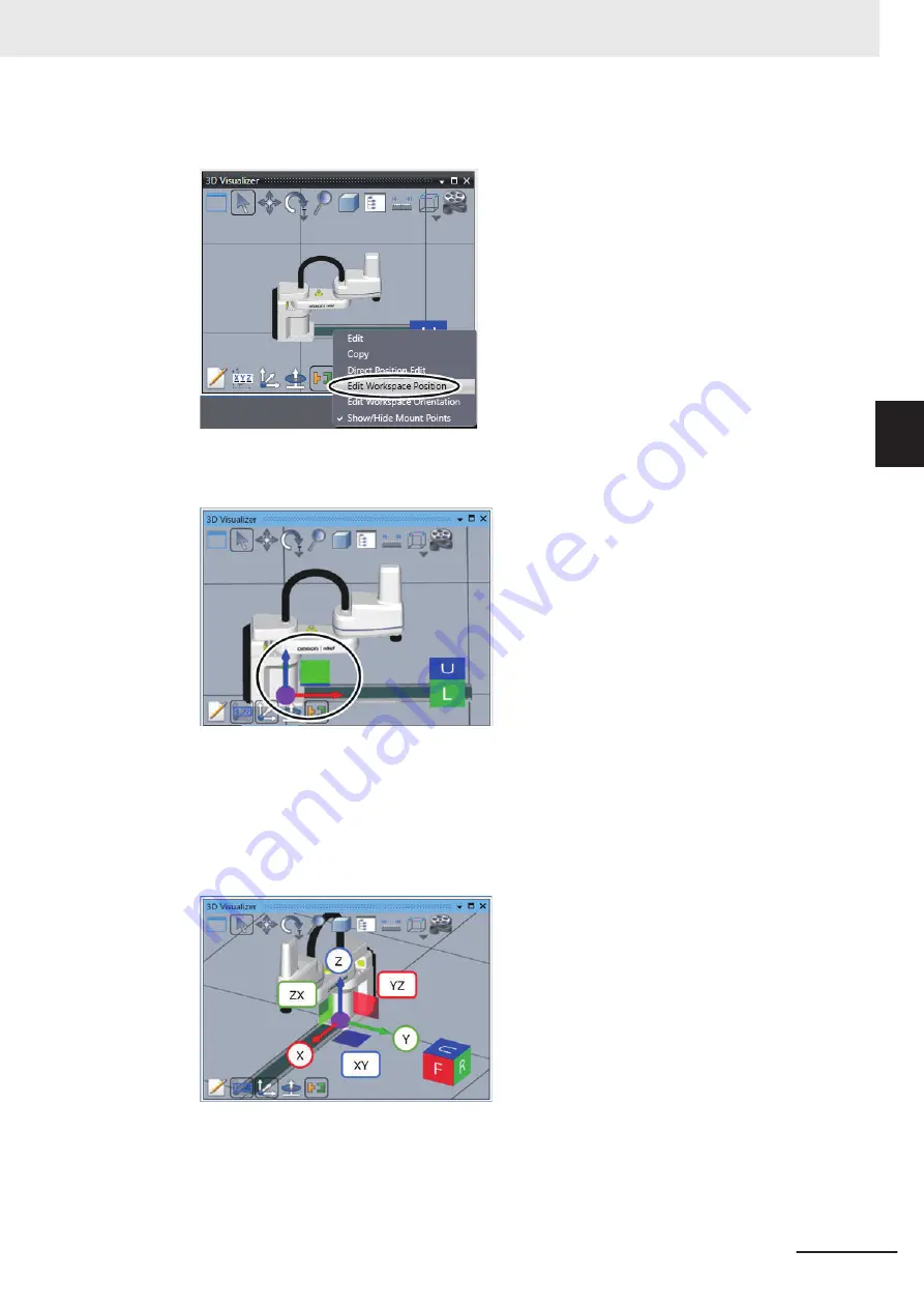
Edit Workspace Position
from the menu.
The Move icon consisting of colored arrows, a purple circle, and faces is displayed on the ori-
gin of the 3D shape data.
4
Drag one of the arrows, faces, or the purple circle and drop it on the place to move the 3D
shape data.
The Move icon has red, green, and blue arrows, which represent the X-axis, Y-axis, and Z-axis,
respectively. The red face shows the YZ plane, the green face shows the ZX plane, and the
blue face shows the XY plane.
You can drag an arrow to move the 3D shape data along the axis. Or, use the face icon to
move the 3D shape data on the corresponding plane. You can also move the 3D shape data
independently from the axis direction by dragging the purple circle.
3 Implementation Example of Static Pick-and-place Equipment
3-43
NJ-series Robot Integrated System Startup Guide (O049)
3-3 Programming and Simulation Procedures
3
3-3-5
Placing 3D Shape Data
Summary of Contents for RL4 Series
Page 4: ...AC1 152000 Introduction 2 NJ series Robot Integrated System Startup Guide O049 ...
Page 23: ...Outline View Detailed View Versions 21 NJ series Robot Integrated System Startup Guide O049 ...
Page 30: ...Revision History 28 NJ series Robot Integrated System Startup Guide O049 ...
Page 42: ...1 Overview 1 12 NJ series Robot Integrated System Startup Guide O049 ...
Page 50: ...2 Before You Begin 2 8 NJ series Robot Integrated System Startup Guide O049 ...
Page 162: ...Appendices A 18 NJ series Robot Integrated System Startup Guide O049 ...
Page 164: ...Appendices A 20 NJ series Robot Integrated System Startup Guide O049 ...
Page 167: ......


