background image

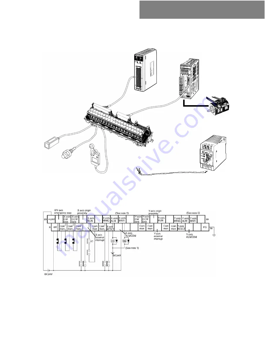
Programmable Controller

Position Control Unit

CS1W-NC413

XW2Z-100J-A7

Dedicated Connection

Cable

XW2B40J62B

Servo Terminal Unit

Servo Driver

R88D-WT01HL

XW2Z-100J-B4

Dedicated Connection Cable

„

Connection Example

2-3. Creating I/O Table

Set CX-Programmer online and create I/O table.

For wiring of junction unit, see W series user’s manual I531-E1 “2-7 Servo Junction Unit 
and Cable Specification”.

*1. The XB contact is used to turn ON/OFF the electromagnetic brake.
*2. Do not connect unused terminals.
*3.The 0 V terminal is internally connected to the common terminals.
*4. The following crimp terminal is applicable: R1.25-3 (round with open end).
*5. Allocate BKIR (Brake Lock) to CN1 pin 27.

2-5 Position Control Unit

CS1W-NC113/133/213/233/413/433 

Summary of Contents for FB LIBRARY -

Page 1: ......

Page 2: ...ct PLC that uses OMRON FB Library and other devices with specific examples This Guide does not include limiting conditions of usage of each unit control component or combination of them Please read us...

Page 3: ...13 233 413 433 2 5 Position Control Unit CS1W NC113 133 213 233 413 433 2 6 Inverter 3G3MV A2 AB A4 3G3RV A2 A4 2 7 Servo Driver R88D WT WT H WT HL R7D AP H AP L 2 8 RFID V600 H 2 9 Vision Sensor F160...

Page 4: ...system as it is Omron is going to add more components to this OMRON FB Library to contribute for higher efficiency and quality of your PLC programming This OMRON FB Library Start Up Guide introduces...

Page 5: ...the OMRON FB Library 3 2 1 Example of using the OMRON FB Library 1 3 2 2 Example of using the OMRON FB Library 2 3 3 Content of the OMRON FB Library 3 3 1 OMRON FB Part Files 3 3 2 Library reference 3...

Page 6: ...al Ladder program for machine A Defining Inputs and Outputs A1 B1 X1 Y1 Z1 Control Device 1 Partial Ladder program for machine A Device Control A B X EN ENO Z Y P_On A2 B2 X2 Y2 Z2 Control Device 2 P_...

Page 7: ...nction block as shown below it is possible to make the time limit of the circuit arbitrary by only changing one specific parameter 2 An Example of a Function Block 2 An Example of a Function Block OMR...

Page 8: ...program operation is unnecessary Omron has tested the Function Block library Debugging the programs for operating the unit and FA components for the PLCs is unnecessary for the user 4 Easy to understa...

Page 9: ...d from the PLC ladder diagram Ability to configure low cost communications RS 232C 485 Serial communications Compoway F protocol Temperature controller Smart sensor Omron Components CS CJ Series PLC A...

Page 10: ...bility to communicate between PLC and DeviceNet slaves easily DeviceNet Inverter Generic slaves such as IO terminal CS CJ series PLC Communicate between PLC and the devices PLC Wireless Temperature co...

Page 11: ...e OMRON FB Library is installed onto a personal computer the OMRON FB Part files are classified in the folder appropriate to each PLC Unit and FA component in the Omron Installation directory 3 3 2 Li...

Page 12: ...nhanced PLC units and FA components The download service of the OMRON FB Library is provided as a menu of Omron Web in each country Type Target components Number of OMRON FB Part files at the time of...

Page 13: ...13 133 213 233 413 433 2 5 Position Control Unit CS1W NC113 133 213 233 413 433 2 6 Inverter 3G3MV A2 AB A4 3G3RV A2 A4 2 7 Servo Driver R88D WT WT H WT HL R7D AP H AP L 2 8 RFID V600 H 2 9 Vision Sen...

Page 14: ...2 1 Controller Link Unit CJ1W CLK21 V1...

Page 15: ...Electric Wire ESVC 0 5 2C 13262 Manufacturer Type Code Shown below are M3 crimping contacts suitable for communication cable O shaped crimping contact with vinyl insulation RAV1 25 M3 O shaped crimpi...

Page 16: ...es on the front panel Setting terminal resistance using DIP switches on the front panel Setting terminal resistance using DIP switches on the front panel 3 Creating I O Table Turning all nodes ON Turn...

Page 17: ...g switch 2 1 2 Unit Number Setting Set the Unit Numbers for node 1 and 2 as described on the left Unit Number 0 As the factory default setting is 0 it is not need to be set 2 1 3 Node Address Setting...

Page 18: ...the unit as shown above and use sliders on the top and bottom of the unit to fix the unit 2 1 7 Wiring Communication Cable Connect all shielded wires to the terminal board and on one end of the netwo...

Page 19: ...perating Green TER terminating resistance Yellow ERC communica tions error ERH PLC error INS network participation Red Red Meaning Unit operating normally Unit error Terminating resistance switch is O...

Page 20: ...8 0003 Hex D30009 0000 Hex Data link participation node 1 node 2 D30010 0000 Hex D30011 0000 Hex D30000 0010 Hex Write the following figures in the each DM parameter areas of node 1 and 2 using CX Pro...

Page 21: ...n Data Link Start Bit Start Changed from OFF to ON or set to ON when power is turned ON Stop Changed from ON to OFF 0 Always set to 0 Leftmost digit of data link start word of area 2 BCD 00 First data...

Page 22: ...o 0 Local node address 1 Busy Flag W100 00 Normal end W100 01 Error end W100 02 _CLK001_LINK_RunDatalink BOOL EN BOOL ENO INT UnitNo BOOL BUSY INT NodeNo BOOL OK BOOL NG Variables Table INPUT Input Va...

Page 23: ...2 2 DeviceNet Slave DRT2 Series DRT2...

Page 24: ...U unit to read unit conducting period of DeviceNet slave DRT2 series 1 Hardware Configuration 125 Kbps 2 2 DeviceNet Slave DRT2 Series DRT2 Slave PS SYSMAC CS CJ Series Slave Node Address 15 Unit Cond...

Page 25: ...ing Node Address of the slave 2 Wiring Communication Cable and Connecting Master and Slave Wiring DeviceNet communication cables Wiring DeviceNet communication cables Sample program that reads out ope...

Page 26: ...s connector A parallel connector with screws XW4B 05C1 H1 D is provided for node connection 1 Set the master unit number Unit Number Setup Switch In this example unit number is set to 1 The unit numbe...

Page 27: ...rotary switch Node Address Setting One s digit In this example node address is set to 15 The node address must not overlap that of other node master slave in the network 0 to 63 Setup Range 2 digit D...

Page 28: ...an signal and power wires it is harder a little than the net and you can feel it by touching Shielded wire 3 Cut and remove excess shield net remove aluminum tape that covers signal and power wires an...

Page 29: ...nnector tab fits into the node connector 2 2 3 Connecting Communication Power Supply Connect V red and V black of the communication cable to power source DC24V 2 2 4 Creating I O Table Turn all node p...

Page 30: ...Manuals for details on the error codes ExplicitError Explicit message error code May be omitted The FINS error code is output A code of 0000 is output for a normal end Refer to the Related Manuals for...

Page 31: ...2 3 Position Control Unit CJ1W NCF71...

Page 32: ...th speed of 2000 command unit s by relative move command 1 Hardware Configuration Position Control Unit CJ1W NCF71 CPU Unit Power Unit Servo Motor Driver R88D WT MECHATROLINK II Up to 16 axes Servo Mo...

Page 33: ...he PLC ON Turning the PLC ON Connecting the CX Programmer Connecting the CX Programmer Creating I O table Creating I O table Setting common and axis parameters of the Position Control Unit Setting com...

Page 34: ...ervo driver Mount MECHATROLINK II I F units to servo drivers Set their addresses to 1 2 and 3 2 2 Servo Driver Setup Servo Driver W Series W series servo driver requires MECHATROLINK I F unit JUSP NS1...

Page 35: ...on for standard I O signals Connector Terminal Block XW2B 50G5 Connection for MECHATROLINK II Communication Shown below is an example of MECHATROLINK II communication cable connection between a Positi...

Page 36: ...operations of each axis 00H0 Hex DM01000 Description Common Parameter Setup Item Setting DM Channel Common Parameter Write to Position Control Unit Writes common parameter values configured in areas f...

Page 37: ...nd that you use dedicated software WS02 MNTC1 that is easy to set up when you change axis parameters For how to set up parameters using CPU unit s free addresses see documentation W426 E1 4 4 Axis Par...

Page 38: ...ernal input signal assignment through the front panel Notice Procedure Activate setup mode Configure parameter No Indicate parameter value 6541 Input signal selection 5 Pn511 8883 Input signal selecti...

Page 39: ...ackward Drive Inhibit Input Backward Limit Input Signal NOT 43 No assignment Forward Drive Inhibit Input Forward Limit Input Signal POT 42 MING Gain Reduction Input Back to Origin Deceleration LS Orig...

Page 40: ...y 1 cycle Ref Before using this FB servo lock must be ensured Perform servo lock by using another FB s _NCF00_Power before performing the above 2 3 Position Control Unit CJ1W NCF71 Servomotor 1 Axis 1...

Page 41: ...sitioning completed 1 ON FB processed normally 0 OFF FB not processed or ended in an error FB not processed Invalid inputs parameter ended in an error Not finished to read the common parameter ENO ENO...

Page 42: ...2 4 Position Control Unit CJ1W NC113 133 213 233 413 433...

Page 43: ...ition of 2000 command unit with speed of 2000 command unit s by absolute move command 1 Hardware Configuration Power Unit Position Control Unit CJ1W NC413 Driver Cable XW2Z J B7 NC end Cable for Smart...

Page 44: ...le Turning the PLC ON Turning the PLC ON Connecting the CX Programmer Connecting the CX Programmer Creating I O table Creating I O table Setting common and axis parameters Setting common and axis para...

Page 45: ...Unit and servo drivers as shown below 1 S82K 01524 I O Power Supply 1 R7M A03030 Servo Motor 1 R7A CEA003S Motor Connection Cable 1 R7D APA3L Servo Driver SmartStep 1 XW2Z 100J B7 Driver Cable for Sma...

Page 46: ...by automatic or manual tuning Actual unit may require finer adjustment of servo parameters thus you must adjust the unit individually For details see I533 E1 4 2 Switch Setting 4 5 Gain Adjustment an...

Page 47: ...ch or preset beforehand Origin search can be performed another FB s _NCx050_HOME NCx CPU Servo Motor Axis 1 Unit No 0 0 Always ON P_On W1 00 W1 02 Start W1 01 Start W1 02 Done W1 04 Error W1 03 Comman...

Page 48: ...0 OFF FB not started EN EN Description Variable Name Name Variables Table INPUT Input Variables OUTPUT Output Variables Returns the error code when an error has occurred in the FB Refer to the Related...

Page 49: ...2 5 Position Control Unit CS1W NC113 133 213 233 413 433...

Page 50: ...n Control Units for CS series to set up parameters and operation commands Shown below is an example of CS1W NC413 that uses servos for 4 axes performing X axis operation command Servo motor 1 axis con...

Page 51: ...the PLC ON Turning the PLC ON Connecting the CX Programmer Connecting the CX Programmer Creating the I O table Creating the I O table Setting common and axis parameters of the Position Control Unit Se...

Page 52: ...l unit Connection cable and terminal unit depend on the servo driver to be connected For details see W376 E1 3 7 Connection for Servo Terminal Unit Name Type Code Q ty Position Control Unit CJ1W NC413...

Page 53: ...reate I O table For wiring of junction unit see W series user s manual I531 E1 2 7 Servo Junction Unit and Cable Specification 1 The XB contact is used to turn ON OFF the electromagnetic brake 2 Do no...

Page 54: ...y setup If the movement is not good adjust it by automatic or manual tuning To actually use the unit connecting to a machine finer adjustment might be required You must adjust the unit with the machin...

Page 55: ...n search and determine the origin before Notice NCx CPU Servo Motor Axis 1 Unit No 0 0 Always ON P_On W1 00 W1 02 Start W1 01 Start W1 02 Done W1 04 Error W1 03 Command Aborted Servo Motor 1 Axis 1 Un...

Page 56: ...d 0 OFF FB not started EN EN Description Variable name Name Variables Table INPUT Input Variables OUTPUT Output Variables Returns the error code when an error has occurred in the FB Refer to the Relat...

Page 57: ...2 6 Inverter 3G3MV A2 AB A4 3G3RV A2 A4...

Page 58: ...se 200V 3G3RV A2 3G3RV series 3G3RV PDRT2 3 phase 400V 3G3MV A4 Single phase 200V 3G3MV AB 3 phase 200V 3G3MV A2 3G3MV series 3G3MV PDRT2 Type Code Series Remarks Main Unit of Inverter Communication S...

Page 59: ...unication cable between master and slave Connect communication cable between master and slave Wiring communication cable and communication power cables of DeviceNet Wiring communication cable and comm...

Page 60: ...node connection Explanation about each switch 1 Set the master unit number Unit Number Setup Switch In this example unit number is set to 10 A The unit number must not overlap that of other CPU Bus un...

Page 61: ...erter main unit s main circuit and control circuit terminals Complete the wiring for inverter main unit terminal board before mounting the DeviceNet communication unit which will hide the terminal boa...

Page 62: ...here is a grounded terminal to which shielded communication cable is connected Connect this terminal and the inverter s FG terminal 6 Fit the DeviceNet communication unit s connector and the inverter...

Page 63: ...base of the inverter main unit 5 Fit the option card connector and the controller board connector on the right position insert the spacer on the card s spacer hole Press the spacer into the hole until...

Page 64: ...node address of 3G3MV is set to 15 and that of 3G3RV is set to 30 The node address must not overlap that of other node master slave in the network See bellow for the Switch location Switch location fo...

Page 65: ...le than the net and you can feel it by touching 3 Cut and remove excess shield net remove aluminum tape that covers signal and power wires and peal the sheath of signal and power wires for crimping te...

Page 66: ...Supply Connect V red and V black of the communication cable to power source DC24V 2 4 Creating I O Table Set CX Programmer online and create I O table Communication power supply Ground 100 Max 2 3 2...

Page 67: ...Creating and Registering the Scan List 2 6 Inverter 3G3MV A2 AB A4 3G3RV A2 A4 Start Master function 1750 06 ON Turn PLC to Program mode Renew fixed allocation and Scan List Master switch Area Selecti...

Page 68: ...lowing manuals I527 E1 3 1 Operation of Digital Operator I539 E1 4 1 SYSDRIVE 3G3MV Series Set up 2 6 2 3G3RV series Inverter Parameter Setting Description Factory setting Setup figure Name Parameter...

Page 69: ...DRT2 20 DRM CPU Inverter Unit No 10 Area selection 1 10 Speed agreement Contact B Aborted Contact C Error end Contact D Error number Always ON Area selection 1 Master Unit No 10 Inverter slave addres...

Page 70: ...allocations IN CIO 3700 OUT CIO 3600 1 to 3 1 INT Select Area selection 1 ON FB started 0 OFF FB not started BOOL EN EN Description Range Default Data type Variable name Name Variables Table INPUT Inp...

Page 71: ...2 7 Servo Driver R88D WT WT H WT HL R7D AP H AP L...

Page 72: ...er PC Power Supply Unit CJ Series CPU Unit Servo Driver W Series Servo Motor Communication Cable XW2Z J C1 Serial Communication Unit CJ1W SCU41 Up to 15 servo unit can be connected Servo Terminal Bloc...

Page 73: ...f Serial Communication Unit 2 Creating I O table Turn PLC power supply ON Turn PLC power supply ON Connecting CX Programmer Connecting CX Programmer Creating I O table Creating I O table Restarting th...

Page 74: ...t of CPU and peripheral port can not be used Use RS422 485 communication port When using RS232 port a level converter CJ1W CIF11is needed Power Supply Unit CJ Series CPU Unit Serial Communication Unit...

Page 75: ...Switch Terminal Resistance ON OFF Switch 2 lines 4 lines Shifting Switch Set the unit number to 5 using flat blade screw driver RS232C Port 2 Unit No Setting Switch Unit No Setting Switch RS232C Port...

Page 76: ...ameters at the serial communication unit is reflected when power supply is restarted from the OFF position 2 3 1 Parameter Setting If you use macro with the above D32000 D32010 m m 10 must be 8604 Set...

Page 77: ...t the rotary switches shown bellow Unit No 3 and 4 Unit No Setting Switch Set unit No to 3 and 4 using flat bladed screw drive Servo Motor Servo Motor Servo Motor Servo Motor Unit No 3 Unit No 4 Unit...

Page 78: ...Series Set the unit No with the parameter by digit 2 of Pn000 2 to 6 Set the unit No with the parameter by digit 2 of Pn000 2 to 5 2 7 Servo Driver R88D WT WT H WT HL R7D AP H AP L Operation Procedur...

Page 79: ...series Servo Driver connected with Serial Communication Unit No 5 R88D WT WT H WT HL R7D AP H AP L Busy Flag W100 00 Normal end W100 01 Error end W100 02 Error Code W101 Read value W102 SCU SCB Select...

Page 80: ...rrorID Error code 0 OFF Other end status 1 ON One of the following error occurred x CMND instruction could not be executed other message being processed x An input variable is out of range x The corre...

Page 81: ...D AP__L Single phase 200V 3 phase 200V R7D AP__H SmartStep A Series R88D WT__HL R88D WT__HL Single phase 200V 3 phase 200V R88D WT__H R88D WT___H W Series Type Code Type Code RS232 2 ports CS1W SCU21...

Page 82: ...ommunication Servo Terminal Unit with Communication Name Name Name Communication Cable for Serial Communication Unit Communication Cable for Serial Communication Unit Communication Cable for Serial Co...

Page 83: ...ecified cable In this case it is helpful to use terminal resistance switch on servo terminal board rather than RT terminal RXD RDB CJ1W CIF11 R7D APA5L Terminal Resistance CJ1W SCU Port1 RDA SDB SDA R...

Page 84: ...2 8 RFID ID Sensor V600 H...

Page 85: ...ece and reads the data again 1 Hardware Configuration 2 8 RFID ID Sensor V600 H For CJ series CPU Unit ID Sensor Unit Read Write Head Data Carrier Work Moved object Work Moved object Moved Shown above...

Page 86: ...nnecting the read write head to the ID sensor unit 2 Software Setup of ID Sensor Unit Setting ID sensor unit operation Setting ID sensor unit operation 4 Usage Example of FB Component Sample program t...

Page 87: ...he connector holding the rubber hold part as the connector is not locked when pressed holding the ring part 1 Hold the rubber hold part of the connector and insert the connector in align with the key...

Page 88: ...istence error signal Communication mode setting Setting with or without verification when writing Operation mode switch setting Unused Description Auto stop waiting time setting System setting Setting...

Page 89: ...set to ON by 1 cycle Unit No 1 Head No 1 Data Carrier write address 10 Bytes to process in Data Carrier 4 Write data storage area type P_DM Write data storage word address 1000 Communications designat...

Page 90: ...ill be performed and a normal end will be output for 0 Consider the Data Carrier capacity when setting WriteBytes Bytes to process in Data Carrier Specify the address in the Data Carrier CarrierAddres...

Page 91: ...arning 007C Head error 007D Write protection error FFFF Input parameter error ErrorCode Error code May be omitted Turns ON for one cycle when processing ends in an error NG Error end Turns ON for one...

Page 92: ...ntact W1 03 is set to ON by 1 cycle Unit No 1 Head No 1 Data Carrier read address 10 Bytes to read from Data Carrier 4 Read data storage area type P_DM Read data storage word address 2000 Communicatio...

Page 93: ...ata Carrier capacity when setting Nothing will be performed and a normal end will be output for 0 ReadBytes Bytes to read from Data Carrier Specify the address in the Data Carrier CarrierAddress Data...

Page 94: ...arning 007C Head error 007D Write protection error FFFF Input parameter error ErrorCode Error code May be omitted Turns ON for one cycle when processing ends in an error NG Error end Turns ON for one...

Page 95: ...2 9 Vision Sensor F160 C10...

Page 96: ...15 Recommend S8VS 06024 OMRON This drawing shows connection to CPU unit s built in port Connection is available for serial communication unit board Note 2 9 Vision Sensor F160 C10 Controller F160 C10...

Page 97: ...ensor Wiring communication cable between PLC and Vision Sensor 3 Communication Setup Configuring PLC and Vision Sensor communication setup Configuring PLC and Vision Sensor communication setup 4 Usage...

Page 98: ...sensor 2 1 3 Connect a camera cable to the vision sensor and the camera 2 1 4 Connect a ground cable 2 1 5 Connect a power cable Provide a power supply that satisfies the following conditions DC24V 1...

Page 99: ...ded cable XW2Z 200T 2m XW2Z 500T 5m If you make your own cable its length must be 15 m or shorter 2 2 1 Wiring the RS 232C Communication Cable as shown bellow To Visual Sensor To PLC Signal Pin No FG...

Page 100: ...sion Sensor Setting Vision Sensor Setting None Use with the default factory setup Communication Mode Free Transmission Mode Communication Speed 38400 bps Data Bit Length 8 bits Parity Check None Stop...

Page 101: ...is changed to 7 After normal scene change contact W0 02 is set to ON by 1 cycle If an error occurs by any reason contact W0 03 is set to ON by 1 cycle 2 4 Usage Example of FB Component Busy Flag W0 0...

Page 102: ...Variables Description Variable name Name Turns ON for one cycle when processing ends normally NG Error end Automatically turns OFF when processing is completed OK Normal end 0 OFF FB not processed or...

Page 103: ...er acquisition contact W1 02 is set to ON by 1 cycle and the scene number is outputted to D100 If an error occurs by any reason contact W1 03 is set to ON by 1 cycle Unit selection FFFF Serial Port No...

Page 104: ...s ON for one cycle when processing ends in an error NG Error end Turns ON for one cycle when processing ends normally OK Normal end Automatically turns OFF when processing is completed BUSY Busy Flag...

Page 105: ...2 10 2D Code Reader V530 R2000 R160 R150V3...

Page 106: ...D Code Reader V530 R2000 R160 R150V3 This drawing shows connection to CPU unit s built in port Connection is available for serial communication unit board Notice Monitor F150 M05L Console F150 KP Cons...

Page 107: ...and 2DCR 3 Communication Setup Configuring communication setting of PLC and 2DCR Configuring communication setting of PLC and 2DCR 4 Setting Code Reader Readout Condition Configure readout condition...

Page 108: ...2 1 3 Connect a camera cable to 2DCR and a camera 2 1 4 Connect a ground cable 2 1 5 Connect a power cable Provide a power supply that satisfies the following conditions DC24V 10 15 1 6A or more Sourc...

Page 109: ...32C port of the CPU unit Recommended Cable XW2Z 00T 2 m XW2Z 500T 5 m 9 SG GND 5 CS CTS 4 RS RTS 3 RD RXD 2 SD TXD Pin No Signal 9 5 4 3 2 Pin No SG GND CS CTS RS RTS RD RXD SD TXD Signal If you make...

Page 110: ...e Transmission Mode Communication Mode PLC Setting PLC Setting Activate CX Programmer then click PC System Setup icon PC System Setup screen pops up 2D Code Reader Setting 2D Code Reader Setting None...

Page 111: ...he initial screen appears The following screen appears the first time power is turned ON 2 Use the camera to take a picture Be sure that the 2 dimensional code is correctly displayed within the field...

Page 112: ...to MON monitor using the Right Key and press the ENT Key The mode selections are displayed Move to SET using the Up Key and press the ENT Key The following screen is displayed The screen is in SET mo...

Page 113: ...elect Reading Settings QR Teaching Select the required symbol color Black Black symbol printed on white base Press the ESC Key to return to the window shown in step 7 Use the Up Down Keys to select th...

Page 114: ...step 7 It is possible to view and if necessary change the parameter setting in Reading Settings Manual If reading is not performed correctly NG the teaching function will stay ON To turn the teaching...

Page 115: ...1000 If an error occurs by any reason contact W0 03 is set to ON by 1 cycle Busy Flag W0 1 Normal end W0 2 Error end W0 3 W0 0 W0 1 Unit selection FFFF Serial Port No 1 Storage order designation 0 Are...

Page 116: ...CPU Unit memory 0010 01 02 01 0011 02 04 03 0012 03 0013 04 Area for read results RecvAreaID P_CIO 00B0 CIO Area P_WR 00B1 Work Area P_HR 00B2 Holding Area P_DM 0082 DM Area P_EM0 0050 to P_EMC 005C...

Page 117: ...ENO May be omitted ENO 1 ON FB processed normally 0 OFF FB not processed or ended in an error Busy Flag BUSY Automatically turns OFF when processing is completed Normal end OK Turns ON for one cycle...

Page 118: ...2 11 Smart Sensor ZX SF11 ZX LD40 ZX LDA11 N...

Page 119: ...re Configuration To CPU build in communication board Sensor Head ZX LD40 Detected Object Automatic teaching 2 11 Smart Sensor ZX SF11 ZX LD40 ZX LDA11 N This drawing shows connection to CPU unit s bui...

Page 120: ...communication cable between PLC and the interface unit Wiring communication cable between PLC and the interface unit 2 Wiring Communication Cable and Connecting to the Unit 3 Communication Setup Conf...

Page 121: ...ck whether the current voltage changing switch on the bottom of the interface unit is under initial state set to a position without a spike 2 1 2 Amplifier Unit Setting Change the amplifier unit to RU...

Page 122: ...he amplifier unit and insert interface unit into amplifier unit connector 2 2 3 Connecting Power Cable to Smart Sensor Connect DC12V 24V 10 power source to brown 1 and 0V to blue 2 2 2 4 Wiring Commun...

Page 123: ...2 2 5 Communication Cable Connection Connect the interface unit communication cable and the built in RS232C port of the CPU unit 2 11 Smart Sensor ZX SF11 ZX LD40 ZX LDA11 N...

Page 124: ...s shown above Then connect PLC online and transmit the PC system setup Smart Sensor Setting Smart Sensor Setting None Use with the default factory setup Communication Mode Serial gateway mode Communic...

Page 125: ...tomatic teaching is terminated After normal automatic teaching contact W1 02 is set to ON by 1 cycle and these HIGH and LOW threshold values are stored in D0 D1 and D2 D3 Busy Flag W0 01 Normal end W0...

Page 126: ...escription Variable name Name Specify the connection Unit and the serial port PortNo Serial Port No UnitSelect Unit selection 1 ON FB started 0 OFF FB not started EN EN Description Variable name Name...

Page 127: ...value from the Smart Sensor Busy flag W2 01 Normal end W2 02 Error end W2 03 Threshold D0 Unit selection FFFF Serial Port No 1 _ZXL207_ReadHighThreshold BOOL EN BOOL ENO INT UnitSelect BOOL BUSY INT P...

Page 128: ...al end Automatically turns OFF when processing is completed BUSY Busy Flag 1 ON FB processed normally 0 OFF FB not processed or ended in an error ENO ENO May be omitted Description Variable name Name...

Page 129: ...2 12 Temperature Controller E5ZN 2...

Page 130: ...is available for serial communication unit board Note 2 12 Temperature Controller E5ZN 2 Attachment Adapter K32 23209 Communication Converter K3SC 10 SYSMAC CS CJ Series Terminal Unit Side Connector...

Page 131: ...tch on front panel Connecting terminal unit Temperature Controller to Terminal Unit Connecting terminal unit Temperature Controller to Terminal Unit Wiring Setting Indicator and Power Cable Wiring Set...

Page 132: ...Connect the power cable to terminals 19 20 on the temperature controller side And to terminals 7 8 on the setting indicator side 2 1 3 Wiring Setting Indicator and Power Cable Connect terminal 4 on t...

Page 133: ...able to the communication converter s terminals 1 and 4 Connect SG gray SD orange and RD white of attachment adapter K32 23209 to the communication converter s terminals 3 5 and 6 respectively 1 If th...

Page 134: ...t adapter and SD signal of PLC side Cable length must be 15 m or less 2 2 2 Connect the attachment adapter to the built in 232C port of the CPU unit L H 64IN To attachment adapter To PLC Signal Pin No...

Page 135: ...setup Temperature Controller Setting Temperature Controller Setting None Use with the default factory setup Communication Mode Serial gateway mode Communication Speed 9600 bps Data Bit Length 7 bits...

Page 136: ...oller s unit number 1 After normal readout termination contact W0 02 is set to ON by 1 cycle and the current values are outputted to D100 If an error occurs by any reason contact W0 03 is set to ON by...

Page 137: ...annel 1 2 Channel 2 E5CN E5CN U Always 1 ChannelNo Channel No Specify the unit number of the Controller E5AR E5ER 0 to 99 E5ZN 0 to 15 0 to F E5CN E5CN U 0 to 99 TCNo Controller unit No PortNo Serial...

Page 138: ...nal variables Error Code Description 2 12 Temperature Controller E5ZN 2 Outputs result information of the command to the temperature controller See below for details ErrorCode Error Code Description V...

Page 139: ...2 13 Temperature Control Unit CJ1W TC001 101 003 103 002 102 004 104...

Page 140: ...e is a usage example of 4 loop thermocouple NPN output type type code CJ1W TC001 and 2 loop platinum thermo resistance with heater disconnection warning NPN output type type code CJ1W TC103 In this ex...

Page 141: ...ng the CX Programmer Connecting the CX Programmer Creating I O table Creating I O table Setting warning mode warning hysteresis range Setting warning mode warning hysteresis range Turning restart flag...

Page 142: ...o 2300 F 0 0 to 500 0 C 0 0 to 900 0 F 100 to 850 C 100 to 1500 F 0 0 to 400 0 C 0 0 to 750 0 F 200 0 to 400 0 C 300 0 to 700 0 F 100 to 850 C 100 to 1500 F 0 0 to 400 0 C 0 0 to 750 0 F 0 to 1700 C 0...

Page 143: ...eration when CPU unit is in PROGRAM mode 1 Factory setting OFF ON Function SW No ON at right Switch function and factory settings 2 1 5 Wiring of thermocouple Connect the wiring based on the following...

Page 144: ...f Warning 2 to 10 deg C Details of these setting items are described in the next page SYSMAC CJ Series D20000 n x100 D20000 n x 100 99 Sending to each unit automatically when power is turned ON or spe...

Page 145: ...Consequently assignment area for loops 3 and 4 is not used and setting is disabled 3 By setting FF for Warning 1 and Warning 2 modes the loop is disabled control operation is terminated and ERC LED c...

Page 146: ...al I O unit assignment DM area Note that exchange of control data for operation is performed for every scanning at I O refreshing of the CPU unit in the order of OUT CPU unit this unit then IN this un...

Page 147: ...oops depends on the Unit LoopNo Loop No UnitNo Unit No 2 Two loop Unit 4 Four loop Unit Select Model selection 1 ON FB started 0 OFF FB not started EN EN Description Variable name Name Description Var...

Page 148: ...Chapter 3 OMRON FB Library List Folder Configuration of The OMRON FB Library List of The OMRON FB Library...

Page 149: ...ry V600 RFID INVRT DNet Inverter Serial SRV ServoDriver CodeReader DCR CPU UNIT SCx ETN CLK PLC Position Controller NCF NC DNet Serial Serial DNet Serial Temperature Controller E5 R E5CN E5ZN TCx Fxxx...

Page 150: ...rter _INVDRT033_MoveVelocityRPM Move Inverter RPM Outputs a run signal rotation direction and speed to the Inverter _INVDRT060_Stop Stop Inverter Stops the Inverter _ INVDRT080_Reset Reset Inverter Er...

Page 151: ...2 point Low Threshold Uses two points to teach the low threshold _ZXL200_ReadMemArea Read Memory Area Reads data from the variable area _ZXL201_ReadMainDisplay Read Main DisplayValue Reads the numeri...

Page 152: ...ON_BIN Binary ON Delay Turns ON the output a specified time after the input turns ON _CPU005_TOF_BCD BCD OFF Delay Turns OFF the output a specified time after the input turns OFF _CPU006_TOF_BIN Binar...

Page 153: ...to the specified Ethernet Unit to receive using a UDP socket _ETN015_SOCKET_UdpSend Send via UDP Socket Issues a request to the specified Ethernet Unit to send using a UDP socket ETN CS1W ETN21 CS1W...

Page 154: ...T Read Present Position Reads the present position of an axis _NCF401_WriteParameter Write Parameter Writes an axis servo parameter _NCF402_WriteBoolParameter Write Boolean Parameter Writes a Boolean...

Page 155: ...put Power Status Reads the power supply status for outputs from slaves connected to DeviceNet _Dnet213_GetLoadShort_Stat Read Load Short circuit Status Reads the load OFF short circuit status from sla...

Page 156: ...erforms a calculation between Data Carrier data and specified data and writes the result to the Data Carrier _V60x405_FillData Fill Data in Data Carrier Writes fill data to a Data Carrier _V60x406_Cop...

Page 157: ...0_WriteVariable Write Variable Area Writes one element to the specified variable area of a Controller on DeviceNet _E5xxDRT403_WriteSP Write Set Point Writes the set point of the specified channel of...

Page 158: ...e Read Variable Area Reads one element from the specified variable area _E5xx201_ReadStatus Read Status Reads the status of the specified channel of a Controller _E5xx202_ReadPV Read Process Value Rea...

Page 159: ...area of a Controller on DeviceNet _E5xxDRT403_WriteSP Write Set Point Writes the set point of the specified channel of a Controller connected to DeviceNet _E5xx001_ExeOperation Operation Command Exec...

Page 160: ...xecutes autotuning for the specified loop _TCx005_CancelAT Cancel Autotuning Cancels autotuning for the specified loop _TCx201_ReadStatus Read Status Reads the status of the specified loop _TCx202_Rea...

Page 161: ...xx201_ChangeSceneNo Change Scene Changes the scene _Fxxx202_GetSceneGrNo Get Scene Group Number Gets the scene group number _Fxxx203_ChangeSceneGrNo Switch Scene Group Switches the scene group _Fxxx40...

Page 162: ...Cat No R123 E01 01 Note Specifications subject to change without notice Printed in Japan Authorized Distributor...

Reviews: