Setting System Parameters 2-3
HOW TO START SETUP
To start the Setup utility, follow these steps:
1.
Turn on or reboot your system. Setup displays the
following message:
Press <F2> to enter SETUP
2.
Press
F2
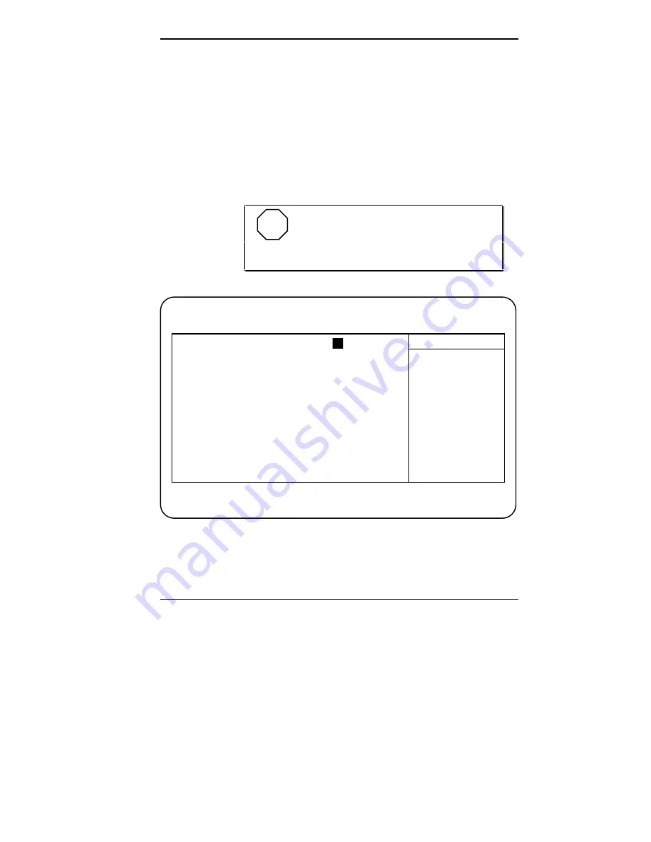
. Setup’s Main Menu window appears similar
to the following screen.
NOTE
The screen shown is typical of your sys-
tem. The actual items on the Main Menu depend
upon the hardware installed in your system.
Main Menu
PhoenixBIOS Setup — Copyright 1992-95 Phoenix Technologies Ltd.
Main Advanced Security Power Exit
System
Time:
[
10
:19:20]
Item Specific Help
System
Date:
[03/12/1995]
Diskette A:
[1.44 MB, 3 ½"]
<Tab>, <Shift-Tab>, or
Diskette B:
[Not Installed]
<Enter> selects field.
> IDE Adapter 0 Master:
C: 540 Mb
> IDE Adapter 0 Slave:
None
> IDE Adapter 1 Master:
None
> IDE Adapter 1 Slave:
None
Video
System:
[EGA/VGA]
> Memory
Shadow:
[Enabled]
> Boot sequence:
[A: then C:]
> Numlock:
[Auto]
System
Memory:
640 KB
Extended
Memory:
7
MB
F1
Help
↑↓
Select
Item
-/+
Change
Values
F9
Setup
Defaults
ESC Exit
←→
Select Menu
Enter Select > Sub-Menu
F10 Previous Values
Summary of Contents for POWERMATE V486 - SERVICE
Page 31: ...1 18 Using Your Computer Minitower fax modem jacks ...
Page 35: ...1 22 Using Your Computer Keyboard supports Keyboard features U S model ...
Page 47: ...1 34 Using Your Computer Loading a CD into the desktop Loading a CD into the minitower ...
Page 131: ...Adding Options 5 15 Removing the screw in the minitower ...
Page 148: ...5 32 Adding Options Locating the cache sockets in the minitower ...
Page 166: ...5 50 Adding Options System board cable connectors in the desktop ...
Page 167: ...Adding Options 5 51 System board cable connectors in the minitower ...
Page 179: ...Adding Options 5 63 Securing the device ...
Page 192: ...5 76 Adding Options Connecting an RS 232C cable to the minitower ...
Page 195: ...Adding Options 5 79 Connecting speaker components ...
Page 200: ...5 84 Adding Options Connecting a telephone line to the desktop ...
Page 205: ...6 4 Setting System Board Jumpers JP3 through JP9 J9 JP11 and JP21 through JP23 jumpers ...
Page 251: ...Sound Board Jumper Settings D 3 Sound board jumper locations and functions ...
Page 255: ...Sound Board Jumper Settings D 7 High DMA channel settings ...


