9 Visualization
Maschinenfabrik Reinhausen GmbH 2020
258
4453918/14 EN
ETOS
®
TD
Property
Options
Function
Function of the analog input (I: ...) or the analog output
(O: ...). You can adjust the designation.
Signal type
Select signal type of analog sensor or deactivate analog
output.
▪ 4...20 mA
▪ PT100-2/3/4, PT1000-2/3/4
▪ Modbus (MR sensor bus)
Card/channel
1)
Select the slot and channel of the analog sensor. Note the
connection diagram supplied.
Unit
1)
Set the unit of the signal.
Decimal places
1)
Set up to three decimal places.
Minimum/maximum
value
2)
Set the minimum and maximum values of the sensor, e.g.
with a 4...20 mA signal, the corresponding measured
value for 4 mA and the corresponding value for 20 mA.
Correction factor
3)
Set the correction factor (m) for the correction of the func-
tion value (x). The corrected function value (y) is:
y = (m * x) + t
Correction offset
3)
Set the offset (t) for the correction of the function value
(x). The corrected function value (y) is: y = (m * x) + t
Table 82: Configuration of the analog inputs and outputs
1)
Only available for GPAI.
2)
Not available with sensors connected over the MR sensor bus (Modbus).
3)
Only available for inputs.
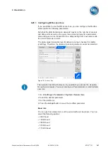
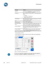
Figure 193: Configuring analog inputs/outputs
You can only change the configuration of the analog inputs and outputs if
you have a Parameter Configurator or Administrator role.
Summary of Contents for ETOS TD
Page 1: ...Motor drive unit ETOS TD Operating Instructions 4453918 14 EN ...
Page 330: ......
Page 332: ......
Page 334: ......
Page 355: ......


