9 Visualization
Maschinenfabrik Reinhausen GmbH 2020
159
4453918/14 EN
ETOS
®
TD
the device responds faster to large voltage changes in the grid. Regulation
accuracy improves as a result but the frequency of tap-changes increases
too.
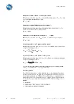
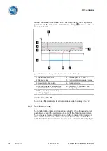
Figure 113: Diagram for integral time response
ΔU/B Control deviation "ΔU" as % of desired value in relation to the set band-
width "B" as % of desired value
1 "Delay time T1" parameter
Delay time T2
You can use this parameter to set delay time T2. Delay time T2 is used to
compensate for large control deviations faster.
The delay time T2 only takes effect if more than one tap-change operation is
required to correct the control deviation. The first output pulse occurs after
the set delay time T1. After the set tap-change delay time T2 has elapsed,
additional pulses occur in order to correct the existing control deviation.
The following requirements must be noted to set delay time T2:
▪ The delay time T2 must be greater than the switching pulse time.
▪ The delay time T2 must be greater than the maximum operating time of
the motor-drive unit.
▪ The delay time T2 must be less than the value set for delay time T1.
Behavior with delay times
T1 and T2
If the control variable
deviates from the set bandwidth for a long period
, a control impulse is output to the motor-drive unit after the set delay time
T1
. If the control variable is still outside the bandwidth, delay time T2
Summary of Contents for ETOS TD
Page 1: ...Motor drive unit ETOS TD Operating Instructions 4453918 14 EN ...
Page 330: ......
Page 332: ......
Page 334: ......
Page 355: ......


