


5 - 32
5 INPUT AXIS MODULE
(2) Via device (Synchronous encoder value input of via device)
(a) Setting method
Used to operate a gray code encoder that is connected to the input module
of the Motion CPU control as a synchronous encoder axis.
By setting "201: Via device" in [Pr.320] Synchronous encoder axis type, the
synchronous encoder is controlled by the encoder value which is the input
value of [Cd.325] Input value for synchronous encoder via device
(10n, 10n).
The encoder value can be used as a cycle counter within the range from 0
to (Resolution of synchronous encoder via device - 1).
Connection is invalid just after the system's power supply is ON. When "1" is
set in [Rq.324] Connection command of synchronous encoder via device
(4n), the synchronous encoder axis current value and the
synchronous encoder axis current value per cycle are restored based on
[Cd.325] Input value for synchronous encoder via device (10n,
10n). Therefore, connection becomes valid, and will be on the
counter enabling status.
The synchronous encoder axis is controlled based on the amount of change
of [Cd.325] Input value for synchronous encoder via device (10n,
10n) while it is connecting.
(b) Setting example
The following shows an example for setting a synchronous encoder via
device as synchronous encoder axis 4.
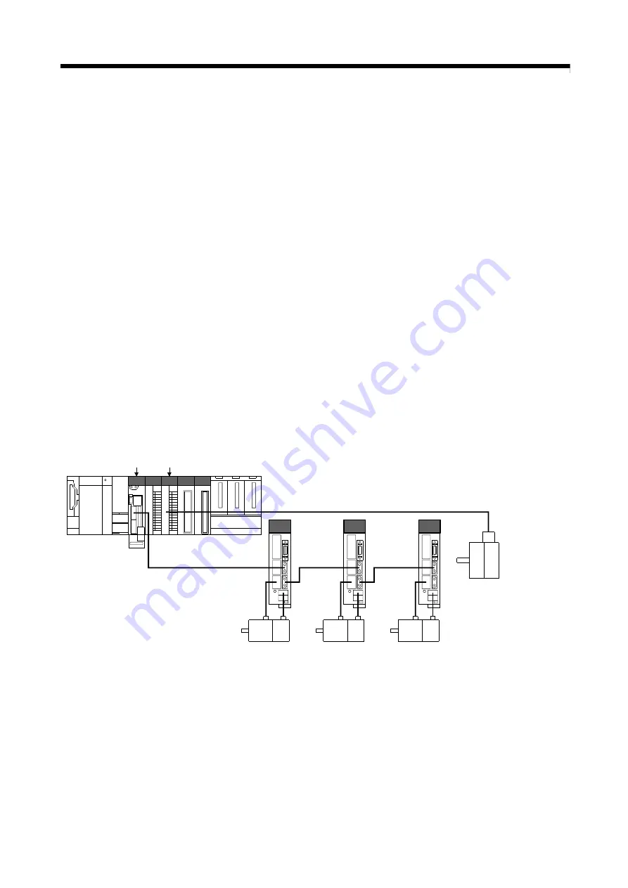
Gray code
encoder
(Resolution 4096)
Synchronous encoder
axis 4
Axis 1
Axis 2
Axis 3
Q173DSCPU Input module
Set the following in [Pr.320]Synchronous encoder axis type and [Pr.329]
Resolution of synchronous encoder via device of synchronous encoder axis
4 on the synchronous encoder axis parameter screen of MT Developer2.
• Type..........................................................................."201: Via device"
• Resolution of synchronous encoder via device........"4096"
Read the encoder value of the gray code encoder with a sequence program,
and update [Cd.325] Input value for synchronous encoder via device
(10n, 10n) of the synchronous encoder axis 4 at every
time.
Summary of Contents for Q172DSCPU
Page 1: ......
Page 19: ...A 18 MEMO ...
Page 39: ...3 4 3 SYNCHRONOUS CONTROL MODULE MEMO ...
Page 129: ...5 50 5 INPUT AXIS MODULE MEMO ...
Page 199: ...7 60 7 SYNCHRONOUS CONTROL MEMO ...
Page 310: ......
Page 311: ......


