Part 2: Review on Replacement of MR-J2S-_A_ with MR-J4-_A_
2 - 33
MR-J2S-_A_
MR-J4-_A_
Control
mode
No.
Name and function
Initial
value
No.
Name and function
Initial
value
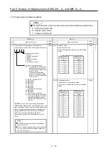
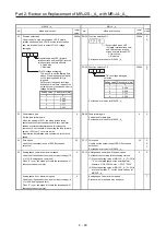
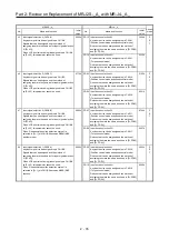
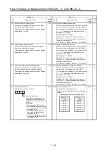
41 Input signal automatic ON selection
Used to set SON (servo-on), LSP (forward rotation stroke
end), and LSN (reverse rotation stroke end) automatic
ON.
0000h PD01 Input signal automatic on selection 1
Used to set input devices to be turned on
automatically.
Refer to the comparison table below for the setting
method.
0000h P
S
T
P
S
42 Input signal selection 1
Assign the input pins for the control mode switching
signals and set CR (clear).
0003h
Input signal selection 1
Assign the input pins for the control mode switching
signals and set CR (clear).
Refer to the comparison table below for the setting
method.
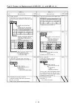
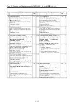
Input signal selection 1 setting comparison table
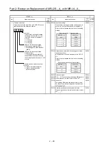
MR-J2S-_A_
MR-J4-_A_
No.42 Target
pin
CR selection
LOP assignment
PD32 Target
pin
Target parameter
Target parameter
No.
Setting value
No.
Setting value
0 0 0 0
CN1B-5
→
0 0 0 0
CN1-15 PD03
2 3 2 3
PD04
0 0 2 3
0 0 0 1
CN1B-14
CN1-19
PD11
PD12
0 0 0 2
CN1A-8
CN1-41
PD13
PD14
0 0 0 3
CN1B-7
CN1-16
PD05
PD06
0 0 0 4
CN1B-8
CN1-17
PD07
PD08
0 0 0 5
CN1B-9
CN1-18
PD09
PD10
0 0 1 0
CN1B-5
0 0 0 1
CN1-15 PD03
2 3 2 3
PD04
0 0 2 3
0 0 1 1
CN1B-14
CN1-19
PD11
PD12
0 0 1 2
CN1A-8
CN1-41
PD13
PD14
0 0 1 3
CN1B-7
CN1-16
PD05
PD06
0 0 1 4
CN1B-8
CN1-17
PD07
PD08
0 0 1 5
CN1B-9
CN1-18
PD09
PD10
0
0
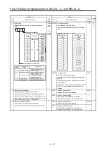
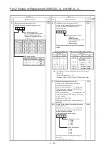
Input pin allocation of LOP
(control change)
Set the input connector pin for the
control method change signal.
However, it is effective if selection of
Position/Speed, Speed/Torque, and
Torque/Position is made in
parameter No.0.
Setting value Connector pin No.
0 CN1B-5
1 CN1B-14
2 CN1A-8
3 CN1B-7
4 CN1B-8
5 CN1B-9
CR (Clear) selection
0: Deleting droop pulses by turning
on the device
1: Always deleting droop pulses
during turning ON of the device
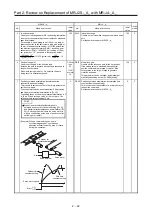
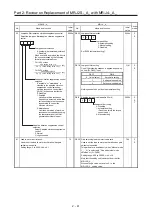
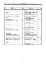
Input signal automatic ON setting
comparison table
MR-J2S-_A_ MR-J4-_A_
No.41 PD01
0 0 0 0
→
0 0 0 0
0 0 0 1
0 0 0 4
0 0 1 0
0 4 0 0
0 0 1 1
0 4 0 4
0 1 0 0
0 8 0 0
0 1 0 1
0 8 0 4
0 1 1 0
0 C 0 0
0 1 1 1
0 C 0 4
0
SON (Servo-on) input
0: ON/OFF by external input
1: Automatic ON in servo amplifier
(External wiring is unnecessary)
LSP input selection
(forward rotation stroke end)
0: ON/OFF by external input
1: Automatic ON in servo amplifier
(External wiring is unnecessary)
LSN input selection
(reverse rotation stroke end)
0: ON/OFF by external input
1: Automatic ON in servo amplifier
(External wiring is unnecessary)
Summary of Contents for MELSERVO-J2-Super Series
Page 18: ...Part 1 Summary of MR J2S MR J2M Replacement 1 1 Part 1 Summary of MR J2S MR J2M Replacement ...
Page 31: ...Part 1 Summary of MR J2S MR J2M Replacement 1 14 MEMO ...
Page 109: ...Part 3 Review on Replacement of MR J2S _B_ with MR J4 _B_ 3 32 MEMO ...
Page 161: ...Part 4 Review on Replacement of MR J2S _CP_ CL_ with MR J4 _A_ RJ 4 52 MEMO ...
Page 239: ...Part 6 Review on Replacement of MR J2M with MR J4 6 20 MEMO ...
Page 240: ...Part 7 Common Reference Material 7 1 Part 7 Common Reference Material ...
Page 284: ...Part 7 Common Reference Material 7 45 Click Update Project ...
Page 342: ...Part 8 Review on Replacement of Motor 8 1 Part 8 Review on Replacement of Motor ...
Page 409: ...Part 8 Review on Replacement of Motor 8 68 MEMO ...
Page 461: ...Part 9 Review on Replacement of Optional Peripheral Equipment 9 52 MEMO ...
Page 462: ...Part 10 Startup Procedure Manual 10 1 Part 10 Startup Procedure Manual ...

