Part 7: Common Reference Material
7 - 14
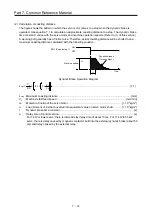
(2) Calculation of coasting distance
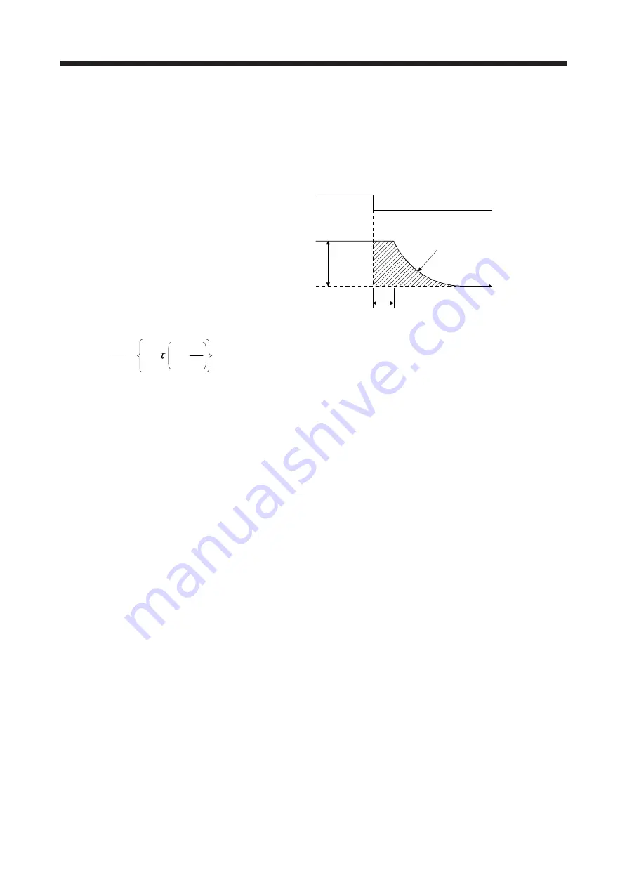
The figure shows the pattern in which the servo motor comes to a stop when the dynamic brake is
operated. Use equation 7.1 to calculate an approximate coasting distance to a stop. The dynamic brake
time constant
τ
varies with the servo motor and machine operation speeds. (Refer to (1) of this section.)
A working part generally has a friction force. Therefore, actual coasting distance will be shorter than a
maximum coasting distance calculated with the following equation.
Dynamic Brake Operation Diagram
L
max
=
60
V
0
x
J
M
t
e
+
1 + J
L
··························································································· (7.1)
L
max
: Maximum coasting distance ..................................................................................................... [mm]
V
0
: Machine's fast feed speed ................................................................................................. [mm/min]
J
M
: Moment of inertia of the servo motor ........................................................................... [× 10
-4
kg•m
2
]
J
L
: Load moment of inertia converted into equivalent value on servo motor shaft ........... [× 10
-4
kg•m
2
]
τ
: Dynamic brake time constant ......................................................................................................... [s]
t
e
: Delay time of control section ........................................................................................................... [s]
For 7 kW or lower servo, there is internal relay delay time of about 10 ms. For 11 kW to 55 kW
servo, there is delay caused by magnetic contactor built into the external dynamic brake (about 50
ms) and delay caused by the external relay.
t
e
V
0
ON
OFF
EM1 (Forced stop 1)
Machine speed
Dynamic brakes
Time constant
t
Time
Summary of Contents for MELSERVO-J2-Super Series
Page 18: ...Part 1 Summary of MR J2S MR J2M Replacement 1 1 Part 1 Summary of MR J2S MR J2M Replacement ...
Page 31: ...Part 1 Summary of MR J2S MR J2M Replacement 1 14 MEMO ...
Page 109: ...Part 3 Review on Replacement of MR J2S _B_ with MR J4 _B_ 3 32 MEMO ...
Page 161: ...Part 4 Review on Replacement of MR J2S _CP_ CL_ with MR J4 _A_ RJ 4 52 MEMO ...
Page 239: ...Part 6 Review on Replacement of MR J2M with MR J4 6 20 MEMO ...
Page 240: ...Part 7 Common Reference Material 7 1 Part 7 Common Reference Material ...
Page 284: ...Part 7 Common Reference Material 7 45 Click Update Project ...
Page 342: ...Part 8 Review on Replacement of Motor 8 1 Part 8 Review on Replacement of Motor ...
Page 409: ...Part 8 Review on Replacement of Motor 8 68 MEMO ...
Page 461: ...Part 9 Review on Replacement of Optional Peripheral Equipment 9 52 MEMO ...
Page 462: ...Part 10 Startup Procedure Manual 10 1 Part 10 Startup Procedure Manual ...


