[Appendix 2] Introduction to Renewal Tool
Appendix 2-86
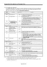
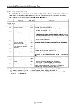
(3) For simultaneous replacement
The following parameters are a minimum number of parameters that need to be set for simultaneous
replacement. Depending on the settings of the currently used servo amplifier, parameters other than
these may need to be set. For details,
refer to Part 2 Section 3.6
.
Parameter
number
Setting item
Setting value
Description
Changing required.
PA04
Function selection A-1
0000h
Forced stop deceleration function selection
To configure the same settings as those for MR-J2S, select "Forced stop
deceleration function disabled (EM1)".
PA09
Auto Tuning Response
8
Auto tuning response setting
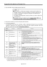
When replacing, switch the power on after setting the parameter value to "8".
*
It is necessary to make gain adjustment again when replacing.
The setting
value of this parameter is equivalent to the slow response of the MR-J2S.
Perform adjustment since tha gain can be too low for the slow response.
For details on how to make gain adjustments, refer to Chapter 6 of the MR-J4
Servo Amplifier Instruction Manual.
PD27
Output device selection 2
* 11 kW or more, only when
using this function
0006h
Dynamic brake interlock (DB) selection)
When using this function for the MR-J2S servo amplifier of 11 kW or more, set the
parameter. Assign a DB signal to pin CN1-48.
PD03 to 14
Input signal device selection
-
When the assignment of the Input/output signal for the existing MR-J2S servo
amplifier, setting is required.
For details, refer to Part 2 Section 3.6.
Position control mode only
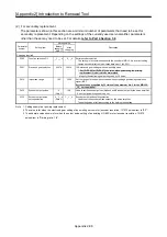
PA06
Electronic gear numerator (CMX)
(Command input pulse
multiplication numerator)
8
(Note 1)
When using an electronic gear, it is necessary to change the setting value.
Set the same value as [Pr. 3] or [Pr. 4] of for the MR-J2S-_A_ servo amplifier.
PA07 Electronic
gear
denominator
(CDV)
(Commanded pulse
multiplication denominator)
1
(Note 1)
PA21
Electronic gear selection
3001h
J2S electronic gear setting value compatibility mode
Magnify the electronic gear setting value by 32 times.
PA13
Command pulse input form
_ 2 _ _ h
Pulse train filter selection
The setting value mentioned at the left side is a command pulse train filter setting
equivalent to the MR-J2S-_A_ (when setting the differential line driver type).
* If it is not set, position mismatch will occur. Make sure to set a filter.
In addition, it is necessary to adjust the command pulse logic to the positioning
module. For details, refer to Part 2 Section 3.7.
* An incorrect logic setting causes the servo motor to not rotate. Make sure
to configure the settings.
PA10
In-position range
100
(Note 2)
In-position range
Used to set an in-position range per command pulse unit.
Set the value of [Pr. 5] for the MR-J2S-_A servo amplifier in this parameter as
well.
Speed control mode only
PA01
Control mode
_ _ _ 2h
Select the servo amplifier control mode.
Select the speed control mode.
PC12
Analog speed command -
Maximum speed
3000
Analog speed command - Maximum speed
The setting value at left is for when the HC-SFS53 motor is replaced with the HG-
SR52 motor.
Torque control mode only
PA01
Control mode
_ _ _ 4h
Select the servo amplifier control mode.
Select the torque control mode.
PC12
Analog speed limit - Maximum
speed
3000
Analog speed limit - Maximum speed
The setting value at left is for when the HC-SFS53 motor is replaced with the HG-
SR52 motor.
PC13
Analog torque command
maximum output
100
Analog torque command maximum output
Set the same value as for the MR-J2S-_A_ servo amplifier.
When using encoder output pulses
PA15
Encoder output pulses
128
(Note 3)
Used to set the encoder pulses (A-phase and B-phase) output by the servo amplifier.
PC19
Encoder output pulse setting
selection
0 _ 1 _ h
(Note 3)
Encoder output pulse setting selection
Used to set the encoder pulses output by the servo amplifier.
The setting value at left is according to the dividing ratio setting.
Note 1. The example value shown is for when the electronic gear setting of an existing servo amplifier is set as "8/1".
2. The example value shown is for when the in-position range of an existing servo amplifier is set as "100".
3. The example value shown is for when the output pulse setting of an existing HC-KFS motor (encoder resolution: 131072
pulses/rev) is "Dividing ratio: 1/4".
Summary of Contents for MELSERVO-J2-Super Series
Page 18: ...Part 1 Summary of MR J2S MR J2M Replacement 1 1 Part 1 Summary of MR J2S MR J2M Replacement ...
Page 31: ...Part 1 Summary of MR J2S MR J2M Replacement 1 14 MEMO ...
Page 109: ...Part 3 Review on Replacement of MR J2S _B_ with MR J4 _B_ 3 32 MEMO ...
Page 161: ...Part 4 Review on Replacement of MR J2S _CP_ CL_ with MR J4 _A_ RJ 4 52 MEMO ...
Page 239: ...Part 6 Review on Replacement of MR J2M with MR J4 6 20 MEMO ...
Page 240: ...Part 7 Common Reference Material 7 1 Part 7 Common Reference Material ...
Page 284: ...Part 7 Common Reference Material 7 45 Click Update Project ...
Page 342: ...Part 8 Review on Replacement of Motor 8 1 Part 8 Review on Replacement of Motor ...
Page 409: ...Part 8 Review on Replacement of Motor 8 68 MEMO ...
Page 461: ...Part 9 Review on Replacement of Optional Peripheral Equipment 9 52 MEMO ...
Page 462: ...Part 10 Startup Procedure Manual 10 1 Part 10 Startup Procedure Manual ...

