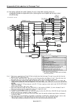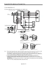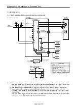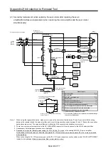
[Appendix 2] Introduction to Renewal Tool
Appendix 2-74
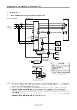
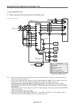
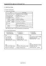
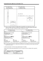
5.5 SC-J2SBJ4KT02K to 3K
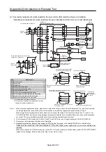
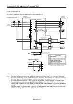
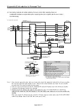
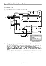
(1) Primary replacement (when replacing the servo amplifier only)
1-phase
100 to 120VAC
The amplifier capacity is 0.4 kW or less
1-phase 100 V connection
1-phase
100VAC
Power supply
for I/F
(24VDC)
⑦
24VDC power supply
connection cable
(Note 3)
For 3-phase 200 V connection
3-phase
200 to 230VAC
Renewal kit
(SC-J2SBJ4KT02 to 3K)
Servo amplifier
(MR-J4-_B(1)-RJ020)
①
④
Encoder
conversion cable
⑤
MR-J2S
servo motor
Encoder
SSCNET conversion unit
(ME-J4-T20)
③
Controller
or servo
amplifier
Servo
amplifier or
termination
resistor
Control signal
conversion cable
⑥
(Note 1)
(Note 2)
(Note 2)
Connection of regenerative option
(for SC-J2SBJ4KT02K to 1K)
Regenerative
option
Regenerative
option
(Note 1)
(Note 1)
(Note 1)
(Note 1)
Make sure to remove the short-circuit bar
between P and D.
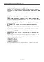
Note 1. When using the regenerative option, make sure to remove the wiring or the short-circuit bar across P (+) and D, connect with
the wiring between the renewal kit and the servo amplifier, and mount the regenerative option between P and C.
When using a built-in regenerative resistor, make sure to connect the wiring or the short-circuit bar across P (+) and D.
For
SC-J2SBJ4KT3K, insulate the wiring between the renewal kit and the servo amplifier. Ensure the connection destinations are
correct. The servo amplifier may malfunction if the connection destinations are incorrect.
2. The N terminal of TE2 is limited to SC-J2SBJ4KT1K and 3K. There is no D terminal wiring for SC-J2SBJ4KT3K.
3. Required only when the internal power supply (24 V DC) for the I/F is used in the existing MR-J2S-_B servo amplifier.
Not included with the renewal tool. Note that a separate 24 V DC power supply (current capacity: 80 mA or more) is required
when replacing.
When connecting the 24 V DC power supply, use the "24 V DC power supply connection cable (model: SC-J2SJ4CTPWC5M)"
included in the package. (Electric wire colors: Red (+ side); white (- side))
Unassigned
Make sure to remove the short-circuit bar
across P and D.
Make sure to remove the wiring
between P+ and D.
Make sure to connect
the wiring between P+
and D.
Make sure to connect the short-circuit bar
across P and D.
(MR-J4-T20)
Summary of Contents for MELSERVO-J2-Super Series
Page 18: ...Part 1 Summary of MR J2S MR J2M Replacement 1 1 Part 1 Summary of MR J2S MR J2M Replacement ...
Page 31: ...Part 1 Summary of MR J2S MR J2M Replacement 1 14 MEMO ...
Page 109: ...Part 3 Review on Replacement of MR J2S _B_ with MR J4 _B_ 3 32 MEMO ...
Page 161: ...Part 4 Review on Replacement of MR J2S _CP_ CL_ with MR J4 _A_ RJ 4 52 MEMO ...
Page 239: ...Part 6 Review on Replacement of MR J2M with MR J4 6 20 MEMO ...
Page 240: ...Part 7 Common Reference Material 7 1 Part 7 Common Reference Material ...
Page 284: ...Part 7 Common Reference Material 7 45 Click Update Project ...
Page 342: ...Part 8 Review on Replacement of Motor 8 1 Part 8 Review on Replacement of Motor ...
Page 409: ...Part 8 Review on Replacement of Motor 8 68 MEMO ...
Page 461: ...Part 9 Review on Replacement of Optional Peripheral Equipment 9 52 MEMO ...
Page 462: ...Part 10 Startup Procedure Manual 10 1 Part 10 Startup Procedure Manual ...

