[Appendix 1] Summary of MR-J4_B_-RJ020 + MR-J4-T20
Appendix 1-29
10. Alarm
10.1 Alarm/Warning List
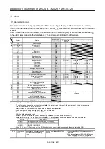
When an error occurs during operation, an alarm or a warning is displayed. When an alarm or a warning
occurs, take the proper action as described in the "MR-J4-_B_RJ020/MR-J4-T20 Servo Amplifier Instruction
Manual".
After removing the cause of the alarm, the alarm can be canceled using any of the methods marked with
○
in the alarm reset column in the table below. (The shaded parts indicate the differences.)
Number Name
Stop method
(Note 6)
Reset alarm
Power-off to
power-on
Reset an error
Reset the CPU
Alarm
10 Undervoltage
EDB
12. _ (Note 5)
Memory error 1
DB
13 Clock
error
DB
15
Memory error 2
DB
16
Encoder error 1
DB
17
Board
error
DB
19. _
Memory error 3
DB
1A
Motor combination error
DB
20
Encoder
error
2
EDB
24
Main circuit error
DB
25
Loss of absolute position
DB
(Note 2)
30
Regenerative
error
DB
(Note 1)
(Note 1)
(Note 1)
31
Overspeed
EDB
32
Overcurrent
DB
(Note 4)
(Note 4)
33
Overvoltage
EDB
34
CRC
error
EDB
35
Command frequency error
EDB
36
Transfer
error
EDB
37
Parameter
error
DB
(Note 4)
3E. 2
Mode change error
DB
(Note 3)
45
Main circuit element overheat
EDB
(Note 1)
(Note 1, 4)
(Note 1, 4)
46
Servo
motor
overheat
DB
(Note 1)
(Note 1)
(Note 1)
50
Overload
1
EDB
(Note 1)
(Note 1)
(Note 1)
51
Overload
2
DB
(Note 1)
(Note 1)
(Note 1)
52
Error
excessive
EDB
8E
Serial
communication
error
EDB
888 Watchdog DB
Warning
92 Battery
disconnection
warning
Warnings are automatically canceled when the cause is
removed.
96
Home position setting error warning
9F Battery
warning
E0 Excessive
regeneration
alarm
E1 Overload
alarm
E3
Absolute position counter alarm
E4
Parameter
alarm
E6
Servo forced stop warning
EDB (Note 7)
E7
Controller emergency stop warning
EDB
E9
Main circuit off warning
DB
EE
SSCNET
error
warning
Note 1. After the cause of the alarm is removed, leave it to cool for about 30 minutes.
2. To confirm connection to the servo system controller, the alarm may not be reset if the power is not turned on twice or more.
3. It is only reset when mode is set correctly.
4.
Alarm factors may not be removed depending on the cause of the alarm.
5. Numerical figures after a decimal point may not be displayed.
6. There are two stop methods of DB and EDB.
DB: Stop with a dynamic brake
EDB: Stop with an electronic dynamic brake (Only available for the specific servo motor)
Refer to the following table for specific servo motors. The stop method other than the specific servo motor is DB.
Series
Servo
motor
HG-KR
HG-KR053/HG-KR13/HG-KR23/HG-KR43
HG-MR
HG-MR053/HG-MR13/HG-MR23/HG-MR43
HG-SR
HG-SR51/HG-SR52
7. When STO1 or STO2 is turned off (the CN8 short-circuit connector is disconnected), the stop method is DB.
Display Name
Description
Cause
Action
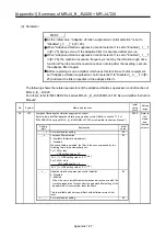
3E.2 Mode
change
error
The operating mode setting does
not match the actual operating
mode.
Switched on with the MR-J4-T20
removed.
1. Connect the MR-J4-T20 and restart the servo
amplifier.
2. With the application of "MR-J4(W)-B Change
mode” supplied with the MR Configurator2,
change to "J2S Compatibility Mode".
Summary of Contents for MELSERVO-J2-Super Series
Page 18: ...Part 1 Summary of MR J2S MR J2M Replacement 1 1 Part 1 Summary of MR J2S MR J2M Replacement ...
Page 31: ...Part 1 Summary of MR J2S MR J2M Replacement 1 14 MEMO ...
Page 109: ...Part 3 Review on Replacement of MR J2S _B_ with MR J4 _B_ 3 32 MEMO ...
Page 161: ...Part 4 Review on Replacement of MR J2S _CP_ CL_ with MR J4 _A_ RJ 4 52 MEMO ...
Page 239: ...Part 6 Review on Replacement of MR J2M with MR J4 6 20 MEMO ...
Page 240: ...Part 7 Common Reference Material 7 1 Part 7 Common Reference Material ...
Page 284: ...Part 7 Common Reference Material 7 45 Click Update Project ...
Page 342: ...Part 8 Review on Replacement of Motor 8 1 Part 8 Review on Replacement of Motor ...
Page 409: ...Part 8 Review on Replacement of Motor 8 68 MEMO ...
Page 461: ...Part 9 Review on Replacement of Optional Peripheral Equipment 9 52 MEMO ...
Page 462: ...Part 10 Startup Procedure Manual 10 1 Part 10 Startup Procedure Manual ...

