Part 2: Review on Replacement of MR-J2S-_A_ with MR-J4-_A_
2 - 26
MR-J2S-_A_
MR-J4-_A_
Control
mode
No.
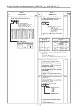
Name and function
Initial
value
No.
Name and function
Initial
value
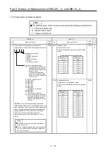
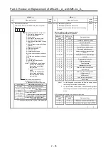
18 Status
display
selection
This is used to select a status display shown at power-
on.
0000h PC36 Status
display
selection
Status display selection at power-on
Refer to the comparison table below for the setting
method.
0000h P
S
T
0
0
Status display selection at power-on
0: Cumulative feedback pulse
1: Servo motor speed
2: Droop pulse
3: Cumulative command pulse
4: Command pulse frequency
5: Analog speed command voltage
(Note 1)
6: Analog torque command voltage
(Note 2)
7: Regenerative load ratio
8: Effective load ratio
9: Peak load ratio
A: Instantaneous torque
B: Within one-revolution position at
low
C: Within one-revolution position at
high
D: ABS counter
E: Load to motor inertia ratio
F: Bus voltage
Note 1: It is for speed control mode.
It will be the analog speed
limit voltage in the torque
control mode.
2: It is for the torque control
mode.
It will be the analog torque
limit voltage in the speed
control mode and position
control mode.
Status display at power-on in
corresponding control mode
0: Depends on the control mode
Control mode
Status display at power-on
Position Cumulative
feedback
pulses
Position/speed
Cumulative feedback pulses/
servo motor speed
Speed
Servo motor speed
Speed/torque
Servo motor speed/
analog torque command voltage
Torque
Analog torque command voltage
Torque/position
Analog torque command voltage/
cumulative feedback pulses
1: Depends on the first digit setting of the parameter
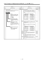
Status display selection comparison table
(1) Status display selection at power-on
MR-J2S-_A_ MR-J4-_A_
Display definition
No.18 PC36
0 0 _ 0
→
0 _ 0 0
Cumulative feedback pulses
0 0 _ 1
0 _ 0 1
Servo motor speed
0 0 _ 2
0 _ 0 2
Droop pulses
0 0 _ 3
0 _ 0 3
Cumulative command pulses
0 0 _ 4
0 _ 0 4
Command pulse frequency
0 0 _ 5
0 _ 0 5
Analog speed command voltage
(Note 1)
0 0 _ 6
0 _ 0 6
Analog torque command voltage
(Note 2)
0 0 _ 7
0 _ 0 7
Regenerative load ratio
0 0 _ 8
0 _ 0 8
Effective load ratio
0 0 _ 9
0 _ 0 9
Peak load ratio
0 0 _ A
0 _ 0 A
Instantaneous torque
0 0 _ B
0 _ 0 B
Within one-revolution position
(1-pulse unit)
0 0 _ C
0 _ 0 C
Within one-revolution position
(100-pulse unit)
0 0 _ D
0 _ 0 D
ABS counter
0 0 _ E
0 _ 0 E
Load to motor inertia ratio
0 0 _ F
0 _ 0 F
Bus voltage
Note 1. It is for the speed control mode. It will be the analog speed
limit voltage in the torque control mode.
2. It is for the torque control mode. It will be the analog torque
limit voltage in the speed control mode and position control
mode.
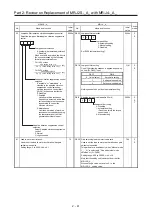
(2) Status display at power-on in each control mode
MR-J2S-_A_ MR-J4-_A_
Display definition
No.18 PC36
0 0 0 _
→
0 0 _ _
Depends on each control mode
0 0 1 _
0 1 _ _
Depends on the second digit of PC36.
Summary of Contents for MELSERVO-J2-Super Series
Page 18: ...Part 1 Summary of MR J2S MR J2M Replacement 1 1 Part 1 Summary of MR J2S MR J2M Replacement ...
Page 31: ...Part 1 Summary of MR J2S MR J2M Replacement 1 14 MEMO ...
Page 109: ...Part 3 Review on Replacement of MR J2S _B_ with MR J4 _B_ 3 32 MEMO ...
Page 161: ...Part 4 Review on Replacement of MR J2S _CP_ CL_ with MR J4 _A_ RJ 4 52 MEMO ...
Page 239: ...Part 6 Review on Replacement of MR J2M with MR J4 6 20 MEMO ...
Page 240: ...Part 7 Common Reference Material 7 1 Part 7 Common Reference Material ...
Page 284: ...Part 7 Common Reference Material 7 45 Click Update Project ...
Page 342: ...Part 8 Review on Replacement of Motor 8 1 Part 8 Review on Replacement of Motor ...
Page 409: ...Part 8 Review on Replacement of Motor 8 68 MEMO ...
Page 461: ...Part 9 Review on Replacement of Optional Peripheral Equipment 9 52 MEMO ...
Page 462: ...Part 10 Startup Procedure Manual 10 1 Part 10 Startup Procedure Manual ...

