[Appendix 1] Summary of MR-J4_B_-RJ020 + MR-J4-T20
Appendix 1-62
13.5.4 Connecting regenerative options
POINT
When using MR-RB50, MR-RB51, MR-RB3M-4, MR-RB3G-4, MR-RB5G-4, MR-
RB34-4, MR-RB54-4, MR-RB3H-4 and MR-RB5H-4, cooling using the cooling
fan is required. You should provide the cooling fan.
Refer to Chapter 7 of this document for wire sizes used for wiring.
Regenerative options may be heated to 100 °C or more above the ambient temperature. Carefully determine
the position of the radiation, installation position, wiring path, etc. Use flame-retardant wire for wiring or apply
flame retardant treatment by avoiding contact between the wires and the regenerative option. Be sure to use
twisted wires when connecting to the servo amplifier and keep the wiring distance to no longer than 5 m.
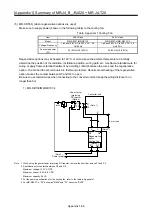
(1) MR-J4-500B-RJ020 or less / MR-J4-350B4-RJ020 or less
Be sure to remove wiring between P+and D and then install the regenerative option between P+ and C.
The G3 and the G4 terminals are thermal sensors. Abnormal overheating of the regenerative option
causes the contact between G3 and G4 to open.
Note 1. When using MR-RB50, MR-RB3M-4, MR-RB3G-4, MRRB5G-4, MR-RB3H-4 and
MR-RB5H-4, perform forced cooling using the cooling fan (1.0 m
3
/min or more, 92
mm square).
2. Provide forced cooling for MR-RB30, MR-RB31 and MR-RB32 using the cooling
fan (1.0
㎥
/min or more, 92 mm square) when the ambient temperature of the
regenerative option is 55 °C and regenerative load ratio exceeds 60%. When the
ambient temperature is at or below 35 °C, the cooling fan is not required. (In the
figure below, it is necessary to cool with the cooling fan required when the
ambient temperature and load ratio are within the shaded area.)
3. Configure sequence of shutting off the electromagnetic contactor when abnormal
heating is caused.
Specifications for contact between G3 and G4:
Maximum voltage: 120 V AC/DC
Maximum current: 0.5 A/4.8 V DC
Maximum capacity: 2.4 VA
100
60
0
0
35
55
Cooling fan is needed
Cooling fan is not
needed
Load ratio [
%
]
Ambient temperature [°C]
D
P+
C
G4
G3
C
P
Servo amplifier
Make sure to remove the wiring between P+ and D.
Regenerative option
(Note 3)
5 m or lower
(Note 1, 2)
Cooling fan
Summary of Contents for MELSERVO-J2-Super Series
Page 18: ...Part 1 Summary of MR J2S MR J2M Replacement 1 1 Part 1 Summary of MR J2S MR J2M Replacement ...
Page 31: ...Part 1 Summary of MR J2S MR J2M Replacement 1 14 MEMO ...
Page 109: ...Part 3 Review on Replacement of MR J2S _B_ with MR J4 _B_ 3 32 MEMO ...
Page 161: ...Part 4 Review on Replacement of MR J2S _CP_ CL_ with MR J4 _A_ RJ 4 52 MEMO ...
Page 239: ...Part 6 Review on Replacement of MR J2M with MR J4 6 20 MEMO ...
Page 240: ...Part 7 Common Reference Material 7 1 Part 7 Common Reference Material ...
Page 284: ...Part 7 Common Reference Material 7 45 Click Update Project ...
Page 342: ...Part 8 Review on Replacement of Motor 8 1 Part 8 Review on Replacement of Motor ...
Page 409: ...Part 8 Review on Replacement of Motor 8 68 MEMO ...
Page 461: ...Part 9 Review on Replacement of Optional Peripheral Equipment 9 52 MEMO ...
Page 462: ...Part 10 Startup Procedure Manual 10 1 Part 10 Startup Procedure Manual ...

