4 Connection
MITSUBISHI CNC
114
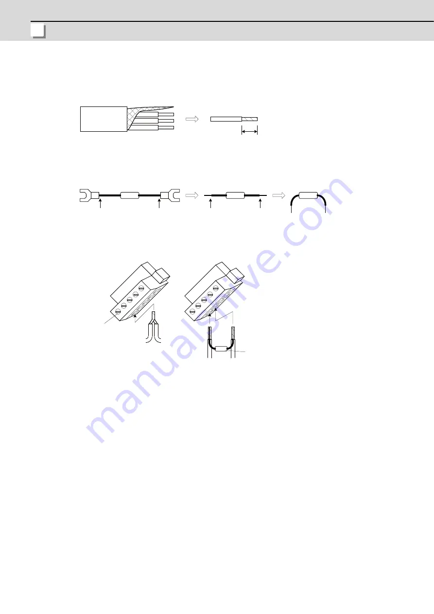
Wiring the cables to the CC-Link terminal block
(1)
Remove the sheath of the cable and isolate each internal wire from the shield mesh.
(2)
Remove the shield mesh and the coat of each internal wire. Twist the core wires.
(3)
In the intermediate station, twist together the same wires or the shield meshes of the cables from/to the
previous/next station.
(4)
In the final station, process the provided terminator as follows to attach to the station.
(5)
Insert the core wire into the opening of the terminal block. Hold the wire tight with a flat-blade screwdriver.
Check the screws on the terminal are loose enough before inserting the wires into the openings.
(6)
After wiring cables to the terminal block, Mount the terminal block into the CC-Link connector and fix it with a
flat-blade screwdriver.
7mm
Approx.
Shield mesh
Shielded twisted cable (with 3 wires)
Terminator
Shorten the
coated part
Bend the lead wires
Cut
Cut
(Note 1)
Do not solder-plate the core wire,
which leads a defective cable contact.
(Note 2)
Make sure the lead wires are kept inserted
when mounting the terminator.
DA wire
DB wire
Terminator
Flat-blade driver
To the
previous
station
To the
next
station
In the intermediate station
In the final station
Summary of Contents for M70V Series
Page 1: ......
Page 13: ......
Page 15: ......
Page 17: ......
Page 19: ......
Page 21: ......
Page 25: ......
Page 26: ...1 1 System Configuration ...
Page 36: ...11 2 General Specifications ...
Page 110: ...85 3 Installation ...
Page 120: ...95 4 Connection ...
Page 173: ...4 Connection MITSUBISHI CNC 148 ...
Page 174: ...149 付録 Ap 1 章 149 Appendix 1 Cable ...
Page 220: ...195 付録 Ap 2 章 195 Appendix 2 EMC Installation Guidelines ...
Page 232: ...207 付録 Ap 3 章 207 Appendix 3 Restrictions for Lithium Batteries ...
Page 241: ...Appendix 3 Restrictions for Lithium Batteries MITSUBISHI CNC 216 ...
Page 242: ...217 付録 Ap 4 章 217 Appendix 4 Precautions for Compliance to UL c UL Standards ...
Page 246: ......
Page 250: ......


