2 General Specifications
MITSUBISHI CNC
50
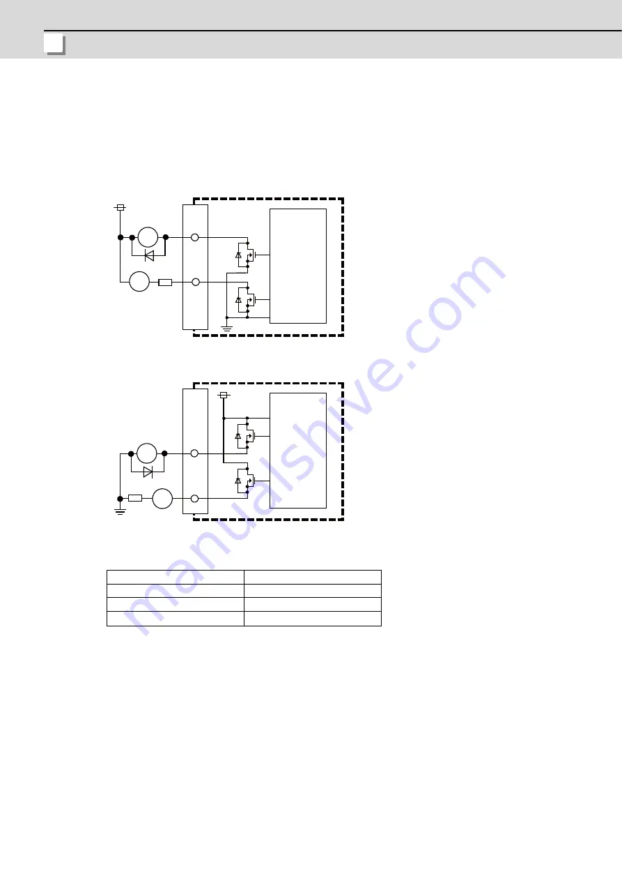
(3) Machine output (DO-L)
(4) Machine output (DO-R)
The digital signal output circuit uses a sink type (DX1x0) or source type (DX1x1).
Use within the specification ranges shown below.
Output circuit
Output conditions
(Note 1) When using an inductive load such as a relay, always connect a diode (voltage resistance 100V or more,
100mA or more) in parallel to the load.
(Note 2) When using a capacitive load such as a lamp, always connect a protective resistor (R=150
Ω
) serially to
the load to suppress rush currents. (Make sure that the current is less than the above tolerable current
including the momentary current.)
Insulation method
Non-insulation
Rated load voltage
24VDC
Max. output current
60mA/point
Output delay time
40
μ
s
R
RA
DO-L/DO-R
PL
R
DO-L/DO-R
RA
PL
Sink type (DX1x0)
Source type (DX1x1)
24VDC(+)
Control
circuit
(Machine side)
Control
circuit
(Machine side)
24VDC(+)
Summary of Contents for M70V Series
Page 1: ......
Page 13: ......
Page 15: ......
Page 17: ......
Page 19: ......
Page 21: ......
Page 25: ......
Page 26: ...1 1 System Configuration ...
Page 36: ...11 2 General Specifications ...
Page 110: ...85 3 Installation ...
Page 120: ...95 4 Connection ...
Page 173: ...4 Connection MITSUBISHI CNC 148 ...
Page 174: ...149 付録 Ap 1 章 149 Appendix 1 Cable ...
Page 220: ...195 付録 Ap 2 章 195 Appendix 2 EMC Installation Guidelines ...
Page 232: ...207 付録 Ap 3 章 207 Appendix 3 Restrictions for Lithium Batteries ...
Page 241: ...Appendix 3 Restrictions for Lithium Batteries MITSUBISHI CNC 216 ...
Page 242: ...217 付録 Ap 4 章 217 Appendix 4 Precautions for Compliance to UL c UL Standards ...
Page 246: ......
Page 250: ......


