4 Connection
MITSUBISHI CNC
146
(b) Spindle override (6bit)
8 position code list
(c) Memory protection switch (1bit)
Memory protection switch X6C
Spare X6D - X6F
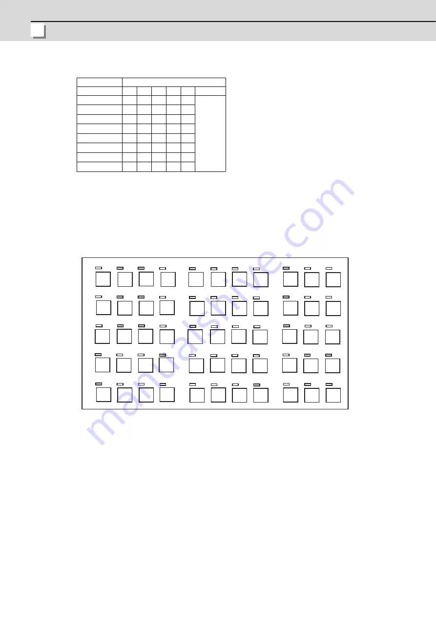
(2) Machine operation panel A (Key switch/LED)
Machine operation panel A is equipped with 55 switches and 55 LEDs.
They are allocated X device and Y device as in the figure below.
(Note1)
If the stations of Machine operation panel and other RIO unit overlap, all the connections of the overlapping
RIOs will be invalidated and cannot be used. Stations which do not overlap can be used.
(Note2)
Refer to the last page "Table: Device No. for Machine operation panel" for the device No. when connecting to
RIO3.
Device No.
Setting value X66 X67 X68 X69 X6A
X6B
0
0
0
0
0
0
Not used
1
0
0
0
0
1
2
1
1
0
0
0
3
0
1
0
0
1
4
0
1
1
0
0
5
1
1
1
0
1
6
1
0
1
0
0
7
0
0
1
0
1
X/Y
80
84
X/Y
83
X/Y
82
X/Y
X/Y
81
X/Y
85
86
87
X/Y
X/Y
X/Y
X/Y
X/Y
X/Y
X/Y
X/Y
X/Y
X/Y
X/Y
X/Y
X/Y
X/Y
X/Y
X/Y
X/Y
88
8C
8D
8E
8F
91
90
92
93
94
95
96
97
98
99
9A
9B
9
9F
9C
X/Y
8B
X/Y
B0
B1
B2
B4
B5
B6
B8
B9
BA
8A
X/Y
X/Y
89
X/Y
9D
X/Y
X/Y
X/Y
X/Y
X/Y
X/Y
X/Y
X/Y
X/Y
X/Y
X/Y
X/Y
X/Y
X/Y
X/Y
X/Y
X/Y
X/Y
X/Y
X/Y
X/Y
X/Y
X/Y
X/Y
X/Y
X/Y
X/Y
E
A1
A0
A2
A3
A4
A5
A6
A7
A8
A9
AA
AC
AD
AE
Summary of Contents for M70V Series
Page 1: ......
Page 13: ......
Page 15: ......
Page 17: ......
Page 19: ......
Page 21: ......
Page 25: ......
Page 26: ...1 1 System Configuration ...
Page 36: ...11 2 General Specifications ...
Page 110: ...85 3 Installation ...
Page 120: ...95 4 Connection ...
Page 173: ...4 Connection MITSUBISHI CNC 148 ...
Page 174: ...149 付録 Ap 1 章 149 Appendix 1 Cable ...
Page 220: ...195 付録 Ap 2 章 195 Appendix 2 EMC Installation Guidelines ...
Page 232: ...207 付録 Ap 3 章 207 Appendix 3 Restrictions for Lithium Batteries ...
Page 241: ...Appendix 3 Restrictions for Lithium Batteries MITSUBISHI CNC 216 ...
Page 242: ...217 付録 Ap 4 章 217 Appendix 4 Precautions for Compliance to UL c UL Standards ...
Page 246: ......
Page 250: ......


