3 Installation
MITSUBISHI CNC
92
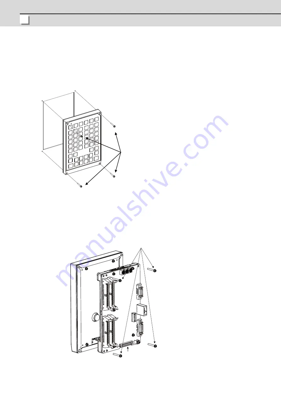
3.3.2 Keyboard Unit
Mount the keyboard unit with four fixing screws.
(Note 1) Refer to "General Specifications: Keyboard Unit" for the panel cut dimension drawing and the screw hole
position.
(Note 2) A clear protective film covers the sheet keys of the keyboard at the time of shipment. Make sure to remove the
sheet before use.
3.3.3 Operation Panel I/O Unit
Mount the operation panel I/O unit on the back of the keyboard unit with four fixing screws.
(Note)
The operation panel I/O unit is usually mounted on the keyboard unit when shipped.
Fixing screws (4)
NCKB
Connector
Fixing screw (4 pcs.) M3x25
(with plain washer and spring washer)
Summary of Contents for M70V Series
Page 1: ......
Page 13: ......
Page 15: ......
Page 17: ......
Page 19: ......
Page 21: ......
Page 25: ......
Page 26: ...1 1 System Configuration ...
Page 36: ...11 2 General Specifications ...
Page 110: ...85 3 Installation ...
Page 120: ...95 4 Connection ...
Page 173: ...4 Connection MITSUBISHI CNC 148 ...
Page 174: ...149 付録 Ap 1 章 149 Appendix 1 Cable ...
Page 220: ...195 付録 Ap 2 章 195 Appendix 2 EMC Installation Guidelines ...
Page 232: ...207 付録 Ap 3 章 207 Appendix 3 Restrictions for Lithium Batteries ...
Page 241: ...Appendix 3 Restrictions for Lithium Batteries MITSUBISHI CNC 216 ...
Page 242: ...217 付録 Ap 4 章 217 Appendix 4 Precautions for Compliance to UL c UL Standards ...
Page 246: ......
Page 250: ......


