2 General Specifications
MITSUBISHI CNC
42
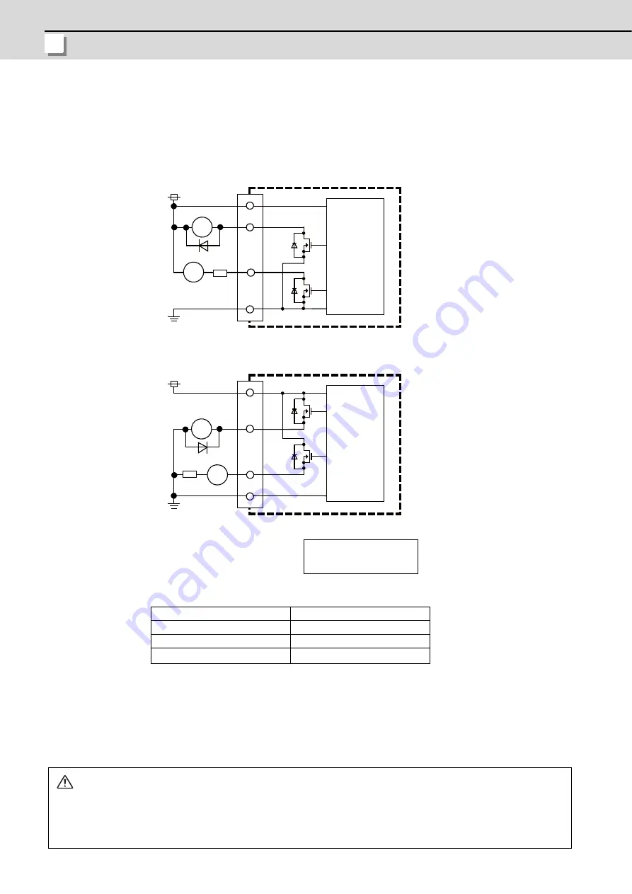
(a) Outline of digital signal output circuit
The digital signal output circuit uses a sink type (DX7x0) or source type (DX7x1).
Use within the specification ranges shown below.
Output circuit
Output conditions
(Note 1) When using an inductive load such as a relay, always connect a diode (voltage resistance
100V or more, 100mA or more) in parallel to the load.
(Note 2) When using a capacitive load such as a lamp, always connect a protective resistor (R=150
Ω
)
serially to the load to suppress rush currents. (Make sure that the current is less than the
above tolerable current including the momentary current.)
Insulation method
Insulation
Rated load voltage
24VDC
Max. output current
60mA/point
Output delay time
40
μ
s
CAUTION
1. When using an inductive load such as a relay, always connect a diode in parallel to the load.
2. When using a capacitive load such as a lamp, always connect a protective resistor serially to the load to
suppress rush currents.
R
RA
CG32/CG34/CG36
PL
R
RA
CG32/CG34/CG36
PL
RA
PL
24VDC(+)
24VDC(+)
Sink type
(DX7x0)
Source type
(DX7x1)
Control
Circuit
(Macine side)
Control
Circuit
(Macine side)
: Relay
: Pilot lamp
Summary of Contents for M70V Series
Page 1: ......
Page 13: ......
Page 15: ......
Page 17: ......
Page 19: ......
Page 21: ......
Page 25: ......
Page 26: ...1 1 System Configuration ...
Page 36: ...11 2 General Specifications ...
Page 110: ...85 3 Installation ...
Page 120: ...95 4 Connection ...
Page 173: ...4 Connection MITSUBISHI CNC 148 ...
Page 174: ...149 付録 Ap 1 章 149 Appendix 1 Cable ...
Page 220: ...195 付録 Ap 2 章 195 Appendix 2 EMC Installation Guidelines ...
Page 232: ...207 付録 Ap 3 章 207 Appendix 3 Restrictions for Lithium Batteries ...
Page 241: ...Appendix 3 Restrictions for Lithium Batteries MITSUBISHI CNC 216 ...
Page 242: ...217 付録 Ap 4 章 217 Appendix 4 Precautions for Compliance to UL c UL Standards ...
Page 246: ......
Page 250: ......


