4 Connection
MITSUBISHI CNC
100
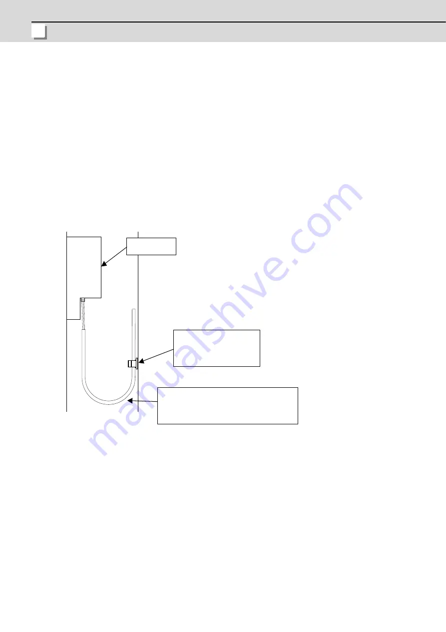
4.1.2.3 Precautions for Laying Optical Communication Cable
(1)
Do not apply a force exceeding the cable's tolerable tension. Binding the cables too tight with tie-wraps could result
in an increased loss or a disconnection. Use a cushioning material such as a sponge or rubber when bundling the
cables and fix so that the cables do not move.
(2)
Do not connect the cables with a radius less than the tolerable bending radius. Excessive stress could be applied
near the connector connection section and cause the optical characteristics to drop. The cable bending radius
should be 10 times or more than the outer diameter at the reinforced sheath, and 20 times or more than the outer
diameter at the fiber cord section.
(3)
Do not apply torsion to the optical communication cable. Laying a twisted cable could cause the optical
characteristics to drop.
(4)
When laying the cables in a conduit, avoid applying stress on the fiber cord and connector connection section. Use
the tensile end such as a pulling eye or cable grip, etc.
(5)
Fix the reinforced sheath with a cable clamp so that the mass of the optical communication cable is not directly
applied on the fiber cord and connector connection section.
(6)
Never bundle the cables with vinyl tape. The plasticizing material in the vinyl tape could cause the POF cable to
break.
(7)
Loop the excessive cable with twice or more than the minimum bending radius.
4.1.3 Precautions for Connecting 24V Power Supply
(1)
When 24V power is supplied to the unit (control unit, display unit) under the following conditions, welding may occur
on the contacts due to rush current; so be careful.
When 24VDC's ON/OFF are directly controlled by a magnetic switch such as relay AND
When heat capacity of the contacts for relay, etc. used to control 24VDC's ON/OFF is small.
CKN-13SP
Recommended clamp material
KITAGAWA INDUSTRIES
Optical communication cable
(section with reinforced sheath):
Bending radius: Refer to the specification of
your optical communication cable.
Control unit
Summary of Contents for M70V Series
Page 1: ......
Page 13: ......
Page 15: ......
Page 17: ......
Page 19: ......
Page 21: ......
Page 25: ......
Page 26: ...1 1 System Configuration ...
Page 36: ...11 2 General Specifications ...
Page 110: ...85 3 Installation ...
Page 120: ...95 4 Connection ...
Page 173: ...4 Connection MITSUBISHI CNC 148 ...
Page 174: ...149 付録 Ap 1 章 149 Appendix 1 Cable ...
Page 220: ...195 付録 Ap 2 章 195 Appendix 2 EMC Installation Guidelines ...
Page 232: ...207 付録 Ap 3 章 207 Appendix 3 Restrictions for Lithium Batteries ...
Page 241: ...Appendix 3 Restrictions for Lithium Batteries MITSUBISHI CNC 216 ...
Page 242: ...217 付録 Ap 4 章 217 Appendix 4 Precautions for Compliance to UL c UL Standards ...
Page 246: ......
Page 250: ......


