8. Connections of I/O Interface
8.4 Connecting with Card-sized I/O Card
123
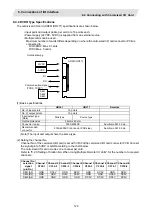
8.4.2 DI/DO Type Specifications
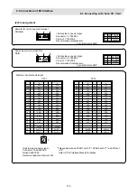
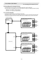
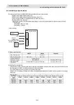
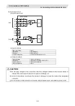
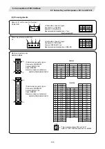
The card-sized I/O card (HR361/HR371) specifications are shown below.
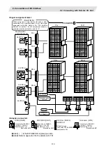
• Input point and output points per card are 16 points each.
• Power supply (24VDC, 5VDC) is supplied from an external source.
• Multiple cards can be used.
Maximum number of cards differs depending on where the card-sized I/O card connector PCB is
connected to:
RIO1/RIO2: Max. 8 cards
RIO3: Max. 5 cards
24VDC
5VDC
DI
DO
HR361/HR371
SEL1
SEL2
SEL3
Outline drawing
Communication signal
(TXRX, TXRX*)
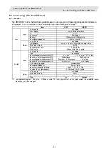
(1) Basic specifications
HR361
HR371
Remarks
No. of input points
16 points
No. of output points
16 points
Input/output type
(Note)
Sink type
Source type
Outline dimension
55mm x 93mm
Connector in use
7650-5002SC
Sumitomo 3M 50 pin
Recommended
connector
9150-4500SC (Connector PCB side)
Sumitomo 3M 50 pin
(Note) The input and output share the same type.
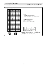
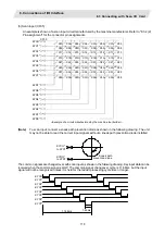
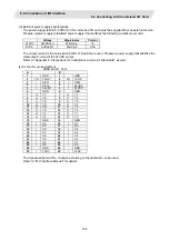
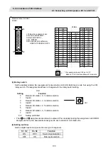
(2) Setting the channel No.
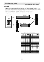
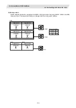
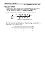
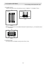
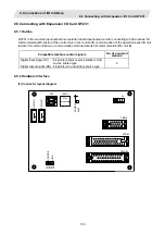
Channel No. of the card-sized I/O card is set with CF30 of the card-sized I/O card connector PCB. Connect
the signal pin to 5VDC or GND according to the chart below.
The card-sized I/O card occupies one channel per card.
Refer to "8.2.3 Setting of Station No. When Using Multiple Remote I/O Units" for the number of occupied
channels.
Channel No.
selection
signal
(pin No.)
Channel 1
CF30-1
Channel 2
CF30-2
Channel 3
CF30-3
Channel 4
CF30-4
Channel 5
CF30-5
Channel 6
CF30-6
Channel 7
CF30-7
Channel 8
CF30-8
SEL1(A3) GND DC5V GND DC5V GND DC5V GND DC5V
SEL2(B3) GND GND DC5V DC5V GND GND DC5V DC5V
SEL3(A4) GND GND GND GND DC5V DC5V DC5V DC5V


