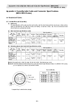


Appendix 4. Servo/Spindle Cable and Connector Specifications (MDS-D/DH)
4.2 Cable Connection Diagram
207
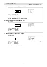
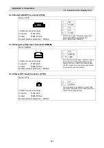
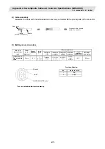
4.2.2 Power Supply Communication Cable and Connector
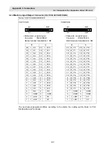
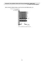
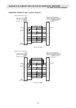
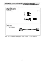
<SH21 cable connection diagram>
Drive unit side connector
Connector: 10120-3000VE
Shell kit: 10320-52F0-008
Power supply unit side connector
Connector: 10120-3000VE
Shell kit: 10320-52F0-008
1
11
2
12
3
13
4
14
5
15
6
16
7
17
8
18
9
19
10
20
PE
1
11
2
12
3
13
4
14
5
15
6
16
7
17
8
18
9
19
10
20
PE
Plate
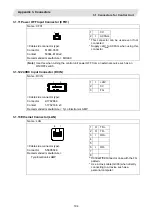
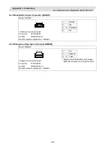
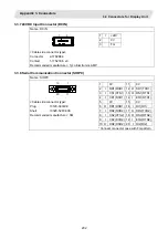
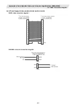
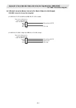
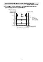
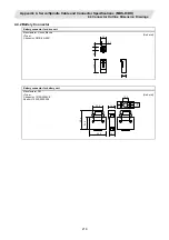
<CNU23S connector connection diagram>
3
1
CN23A
EMG2
EMG1
External emergency
stop input
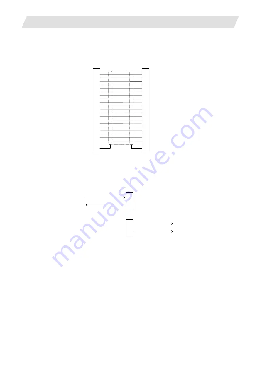
3
1
CN23B
MC2
MC1
Contactor
breaker output
24G
2
2
Power supply unit side connector
Connector: DK-3200M-06RXY
Contact: DK-3REC2LLP1-100