


Appendix 4. Servo/Spindle Cable and Connector Specifications (MDS-D/DH)
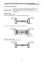
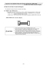
4.2 Cable Connection Diagram
208
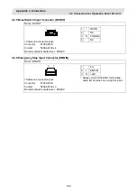
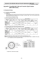
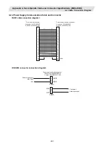
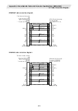
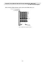
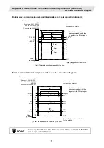
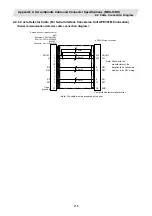
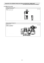
4.2.3 Servo Detector Cable
<CNV2E-6P, CNV2E-7P cable connection diagram>
1
2
9
7
8
3
4
PE
8
5
3
4
6
7
1
2
10
P5(+5V)
LG
BT
SD
SD*
RQ
RQ*
P5(+5V)
LG
-
BT
SD
SD*
RQ
RQ*
SHD
0.5mm
2
Case
grounding
0.2mm
2
0.2mm
2
0.2mm
2
Servomotor detector/
Ball screw side detector side connector
Plug: CM10-SP10S-M (Straight)
CM10-AP10S-M (Angle)
Contact: CM10-#22SC
Servo drive unit side connector
(3M)
Receptacle: 36210-0100PL
Shell kit: 36310-3200-008
(MOLEX)
Connector set: 54599-1019
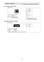
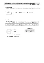
<For 15m or less>
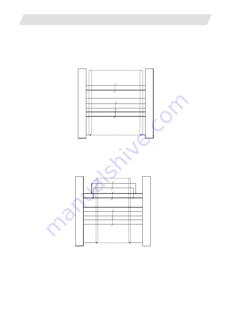
1
2
9
7
8
3
4
PE
8
5
3
4
6
7
1
2
10
P5(+5V)
LG
BT
SD
SD*
RQ
RQ*
P5(+5V)
LG
-
BT
SD
SD*
RQ
RQ*
SHD
0.5mm
2
Case
grounding
0.2mm
2
0.5mm
2
0.2mm
2
0.2mm
2
Servomotor detector/
Ball screw side detector side connector
Plug: CM10-SP10S-M (Straight)
CM10-AP10S-M (Angle)
Contact: CM10-#22SC
Servo drive unit side connector
(3M)
Receptacle: 36210-0100PL
Shell kit: 36310-3200-008
(MOLEX)
Connector set: 54599-1019
<For 15m to 30m>