Appendix 4. Servo/Spindle Cable and Connector Specifications (MDS-D/DH)
4.4 Connector Outline Dimension Drawings
225
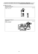
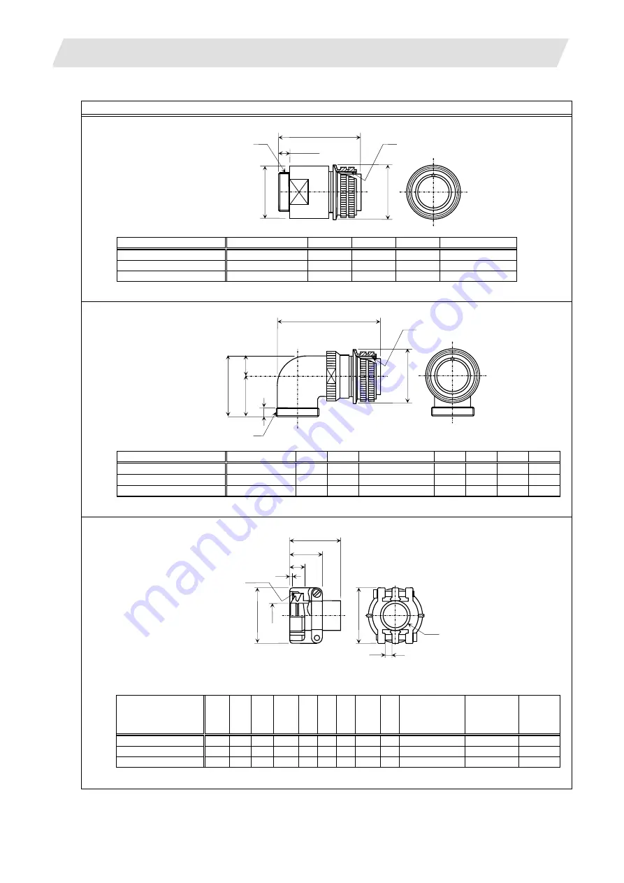
4.4.6 Power Connector
Motor power connector
Manufacturer: DDK
Plug:
[Unit:
mm]
+0
Type
A
B
-0.38
C±0.8
D or less
W
CE05-6A18-10SD-C-BSS
1
1
/
8
-18UNEF-2B 34.13 32.1
57 1-20UNEF-2A
CE05-6A22-22SD-C-BSS
1
3
/
8
-18UNEF-2B 40.48 38.3
61 1
3
/
16
-18UNEF-2A
CE05-6A32-17SD-C-BSS
2-18UNS-2B
56.33
54.2
79
1
3
/
4
-18UNS-2A
Manufacturer: DDK
Plug:
[Unit:
mm]
+0
Type A
B
-0.38
D or less
W
R±0.7 U±0.7 (S)
±1
Y or more
CE05-8A18-10SD-C-BAS 1
1
/
8
-18UNEF-2B
34.13
69.5
1-20UNEF-2A 13.2 30.2 43.4
7.5
CE05-8A22-22SD-C-BAS 1
3
/
8
-18UNEF-2B
40.48
75.5
1
3
/
16
-18UNEF-2A
16.3 33.3 49.6
7.5
CE05-8A32-17SD-C-BAS 2-18UNS-2B 56.33
93.5
1
3
/
4
-18UNS-2A 24.6 44.5 61.9
8.5
Manufacturer: DDK
Clamp:
[Unit:
mm]
Total
length
Outer
dia.
Avail.
screw
length
Fitting
screw
Type
Shell
size
A B
C
D
E
F
G
H
V
Bushing
Applicable
cable
CE3057-10A-1(D240)
18
23.8
30.1 10.3 41.3 15.9 14.1 31.7
3.2
1-20UNEF-2B
CE3420-10-1
φ
10.5
~φ
14.1
CE3057-12A-1(D240)
20
23.8
35
10.3 41.3 19 16.0 37.3
4
1
3
/
16
-18UNEF-2B CE3420-12-1
φ
12.5
~φ
16.0
CE3057-20A-1(D240)
32
27.8
51.6 11.9
43 31.7 23.8 51.6
6.3
1
3
/
4
-18UNS-2B CE3420-20-1
φ
22.0
~φ
23.8
(Movable range of one side)
ø
E
(Inner diameter of cable clamp
)
H
G
±0.7
C
A
V screw
1.6
(B
us
hing inner
diameter
)
ø
F
(D)
B
±0.7
D or less
7.85 or more
W
A
ø
C
±
0.8
-0.38
+0
ø
B
D or less
R
±
0.7
U
±
0.7
(S)
±
1
Y or
more
W
A
-0.38
+0
ø
B

