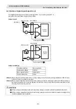
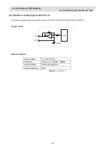
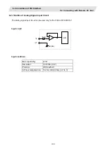

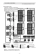
8. Connections of I/O Interface
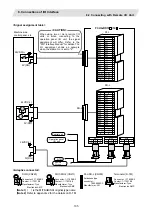
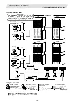
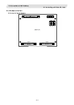
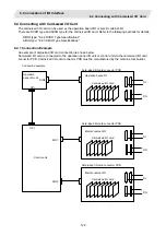
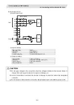
8.3 Connecting with Scan I/O Card
115
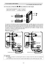
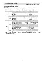
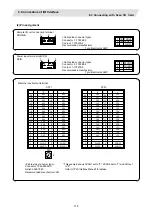
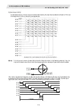
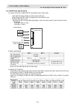
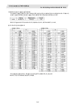
Scan type input/output terminals
B
A
25
GND 25
GND
24 O
LC3B
24 O
LC3A
23 O
LC2B
23 O
LC2A
22
O
LC1B 22
O
LC1A
21 O
LC0B
21 O
LC0A
20 I LD7B* 20 I LD7A*
19
I
LD6B* 19
I
LD6A*
18 I LD5B* 18 I LD5A*
17 I LD4B* 17 I LD4A*
16
I
LD3B* 16
I
LD3A*
15 I LD2B* 15 I LD2A*
14 I LD1B* 14 I LD1A*
13
I
LD0B* 13
I
LD0A*
12
GND 12
11
11
10
10
9 O KYC7* 9 O KYC6*
8
O
KYC5* 8
O KYC4*
7 O KYC3* 7 O KYC2*
6 O KYC1* 6 O KYC0*
5 I KYD7* 5 I KYD6*
4 I KYD5* 4 I KYD4*
3 I KYD3* 3 I KYD2*
2 I KYD1* 2 I KYD0*
1
1 GND
CF35
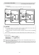
(Note)
The GND pin is not normally used.
Do not connect the GND pin to the frame ground.
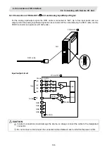
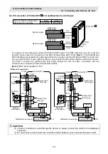
<Cable side connector type>
Connector: 7950-6500SC
Relief: 3448-7950
Recommended manufacturer: 3M
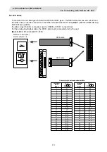
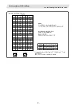
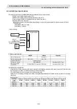
SCAN1
0
2
SCAN2
* This example shows SCAN1 set to "0", SCAN2 set to "1" and
DIO set to "2".
Refer to "PLC Interface Manual" for details.
LCxA/B
Common signal for scan DO
LDxA/B*
Data signal for scan DO
KYCx*
Common signal for scan DI
KYDx*
Data signal for scan DI