


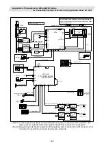


Appendix 6. Precautions for Wiring M700 Series
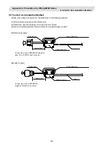
6.5 Ferrite Core Installation Method
251
6.5 Ferrite Core Installation Method
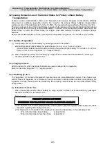
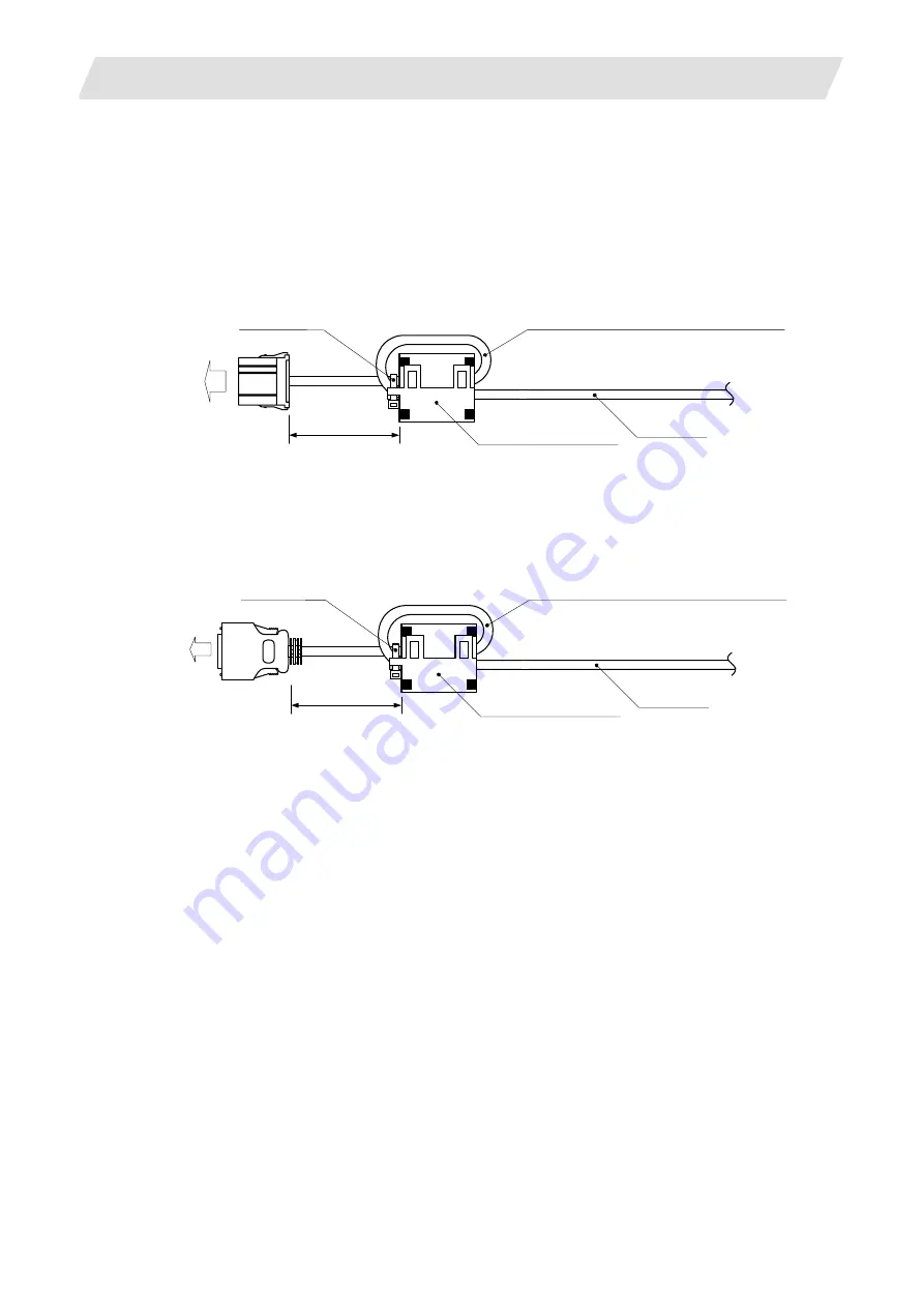
Ferrite cores come with each unit. Connect them in the following manner.
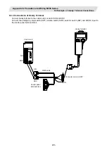
(1) Wind a cable once around the ferrite core.
(2) Attach the case by pressing until a click sound is heard.
(3) Fix with a binding band so that the ferrite core position does not shift.
[24VDC input cable]
Wind a cable once
Cable
Cased ferrite core
Approx. 5cm
Binding band
Connect the cable to MITSUBISHI operation
panel I/O unit 24VDC input connector.
[RS-232C cable]
Wind a cable once
Cable
Cased ferrite core
Approx. 5cm
Binding band
Connect the cable to MITSUBISHI
display unit RS-232C connector.