Structure and Assembly/Disassembly
7-15
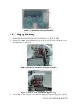
Figure 7-3 Disassembly of Battery (2)
3. Remove panhead screws with washers (5 M3X8 and 2 M3X12) which are installed on the
rack of the main unit rear cover.
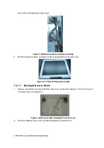
Figure 7-4 Disassembly of Rear Cover Assembly of Main Unit (1)
4. Hold the battery bay and then remove the rear cover of the main unit simultaneously, pull out
the plugs from the battery connecting board.
Summary of Contents for Z6
Page 2: ......
Page 14: ......
Page 16: ...2 2 Product Specifications Left side 9 4 7 5 6 8 ...
Page 72: ......
Page 119: ...Structure and Assembly Disassembly 7 35 图 7 59 Disassembly of Speaker 8 ...
Page 120: ......
Page 132: ......
Page 142: ......
Page 152: ......
Page 168: ......
Page 171: ...Phantom Usage Illustration B 3 ...
Page 172: ......
Page 173: ...P N 046 010452 00 5 0 ...


