4-8 Hardware Principle
4.2.6
Ultrasound System Indicator
CPU
Module
Main board
Power
status
indicator
Power-on status
indicator
Battery status
indicator
AC supply status
indicator
Standby status
indicator
Power
management
FPGA
HDD indicator
driver
5VSTB_CPU
Control panel
+12V
+5V
3.3V
ARM
driver
Power supply
module
IO Board
driver
driver
driver
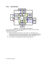
Figure 4-8 Principle Diagram of Ultrasound System Indicator
Function describes as following:
There are four power status indicators on the IO panel: three are used for indicators of
+12V, +5V and 3.3V output on the DC-DC power board, the other one is used for reserved
indicator.
There are five indicators on the control panel, in which power-on status indicator is below
the power button.
AC power-on status indicator control is output by the power management FPGA on the
power module.
The hardware indicator control is output by CPU.
The status indicator of battery are controlled by the battery management ARM on the
power module which driven by 5VSTB on the main board.
The status indicators of power-on and standby are both generated by the battery
management FPGA in the power module and driven by 5VSTB on the main board.
Summary of Contents for Z6
Page 2: ......
Page 14: ......
Page 16: ...2 2 Product Specifications Left side 9 4 7 5 6 8 ...
Page 72: ......
Page 119: ...Structure and Assembly Disassembly 7 35 图 7 59 Disassembly of Speaker 8 ...
Page 120: ......
Page 132: ......
Page 142: ......
Page 152: ......
Page 168: ......
Page 171: ...Phantom Usage Illustration B 3 ...
Page 172: ......
Page 173: ...P N 046 010452 00 5 0 ...


