Hardware Principle 4-7
4.2.5
Ultrasound System
Monitor
CPU
module
Multifunction
FPGA
System
monitor
curcuit
LPC
SMBUS
Temperature
sensor
Main unit front-
end FPGA
temperature
D12V
D-12V
D-5V
D2.5V
D1.8V
D1.5V
D1.2V
Voltage of
clock
battery
Back-end of main board
CPU module
temperature
Main unit fan
Power supply
module fan
Power supply
module
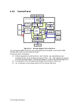
Figure 4-7 Principle Diagram of Ultrasound System Monitor
Ultrasound system monitor is mainly to monitor every voltage of interior machine and temperature.
Function:
On the back-end of the main board, a special monitor IC is used to monitor signal voltages
and clock battery power that are provided to the main board by the main unit box power
supply module.
The system temperature is detected in three positions: BF FPGA, CPU module and power
supply module.
Monitoring chips control the main unit fan and power supply module fan, and then read the
fan rotating,
which send to Multifunction FPGA by smbus, and to PC module by LPC bus.
Summary of Contents for Z6
Page 2: ......
Page 14: ......
Page 16: ...2 2 Product Specifications Left side 9 4 7 5 6 8 ...
Page 72: ......
Page 119: ...Structure and Assembly Disassembly 7 35 图 7 59 Disassembly of Speaker 8 ...
Page 120: ......
Page 132: ......
Page 142: ......
Page 152: ......
Page 168: ......
Page 171: ...Phantom Usage Illustration B 3 ...
Page 172: ......
Page 173: ...P N 046 010452 00 5 0 ...

