Structure and Assembly/Disassembly
7-33
Figure 7-53 Disassembly of Speaker (2)
5. Fasten one M3x12 screw removed (7.2.4.2) into the damping axis adjusting hole of display
about 2-3 rings to confirm that the screw is fixed, then pull out the monitor simultaneously
rotate the display assembly to adjust the monitor to the horizon position.
Figure 7-54 Disassembly of Speaker (3)
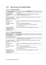
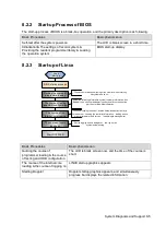
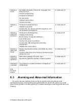
6. Remove 5 panhead screws with washers M3X8 used to fix the front cover and HDD cover,
and then take the HDD cover assembly.
Figure 7-55 Disassembly of Speaker (4)
7. Put the machine on the horizontal position; remove 3 panhead screws with washers M3X8
which are fixed on the rack of the main unit at the bottom of the main unit, take out the main
unit rack assembly.
HDD cover
assembly
Damping axis
adjusting hole
Cables of the speaker
Cables of the
keyboard assembly
Cables of the display
Cables of the ECG
Summary of Contents for Z6
Page 2: ......
Page 14: ......
Page 16: ...2 2 Product Specifications Left side 9 4 7 5 6 8 ...
Page 72: ......
Page 119: ...Structure and Assembly Disassembly 7 35 图 7 59 Disassembly of Speaker 8 ...
Page 120: ......
Page 132: ......
Page 142: ......
Page 152: ......
Page 168: ......
Page 171: ...Phantom Usage Illustration B 3 ...
Page 172: ......
Page 173: ...P N 046 010452 00 5 0 ...


