5-14 Function and Performance Checking Method
NOTE:
1.
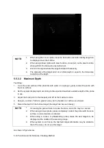
When using the convex probe, keep the transverse resolution testing targets to
be displayed near the midline.
2.
When using a linear probe with steer function, do not turn on the steer function
when perform the transverse resolution test.
3.
Zoom in the region where the targets located if necessary.
4.
The diameter of the target point at a certain depth is equal to the transverse
resolution at the depth.
5.5.2.2
Maximum Depth
Test Step:
1. Cover the scan surface of the phantom with water or couple gel, gently contact the probe with
the scan surface
2. Set the system display depth according to the expected maximum available depth of the probe
in use.
3. Adjust the focus point to the deepest, and AP at the maximum value.
4. Set gain, contrast, TGC at a greater value, but no halation nor defocus is allowed.
5. Record the depth of the furthest target (the target can be seen clearly).
NOTE:
1.
Increasing the gain will also increase the noise, and echo may be covered.
2.
When using a linear probe, please completely contact the probe with the scan
surface, no side clearance is allowed.
3.
When using a convex or phased-array probe, make the axis targets to be
displayed at the middle of the scanning image.
4.
When system is not frozen, the fast field target information may be similar to
that of the noise, do not use this target.
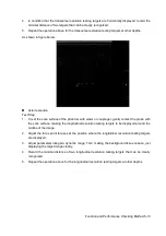
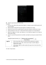
As shown in figure below.
Summary of Contents for Z6
Page 2: ......
Page 14: ......
Page 16: ...2 2 Product Specifications Left side 9 4 7 5 6 8 ...
Page 72: ......
Page 119: ...Structure and Assembly Disassembly 7 35 图 7 59 Disassembly of Speaker 8 ...
Page 120: ......
Page 132: ......
Page 142: ......
Page 152: ......
Page 168: ......
Page 171: ...Phantom Usage Illustration B 3 ...
Page 172: ......
Page 173: ...P N 046 010452 00 5 0 ...


