Structure and Assembly/Disassembly
7-27
Figure 7-37 Disassemble the Control Panel (3)
7.4.7
Display Assembly
1. Remove rear cover assembly of the main unit (referring to 7.4.1 the 1
~
4 step)
2. Remove combination screws (6 M3X8) used to be secured the monitor on the front cover of
the main unit by a screwdriver.
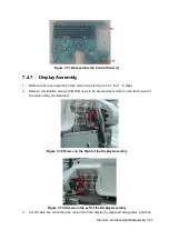
Figure 7-38 Screws on the Right of the Display Assembly
Figure 7-39 Screws on the Left of the Display Assembly
3. Cut off cable ties connecting the main unit on the display by diagonal cutting pliers, and then
Summary of Contents for Z6
Page 2: ......
Page 14: ......
Page 16: ...2 2 Product Specifications Left side 9 4 7 5 6 8 ...
Page 72: ......
Page 119: ...Structure and Assembly Disassembly 7 35 图 7 59 Disassembly of Speaker 8 ...
Page 120: ......
Page 132: ......
Page 142: ......
Page 152: ......
Page 168: ......
Page 171: ...Phantom Usage Illustration B 3 ...
Page 172: ......
Page 173: ...P N 046 010452 00 5 0 ...


