background image

3-18 System Installation 

3.5.6 

System Information 

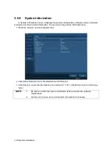
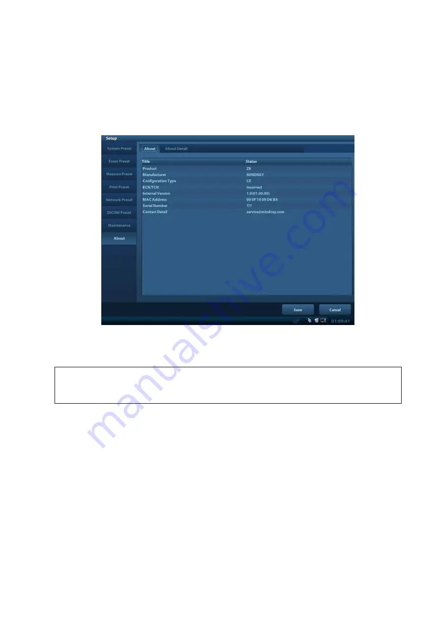
In System Information screen, it displays the product configuration, software version, hardware 

& boards, and driver related information. You can check the product information here. 

1. Press the <Setup> and click [System Info]. 


2. Click [About Detail] to check the detailed board information. 

3. 

Click [Save] to export the information in the format of “*.TXT”; click [Exit] to return to the Setup 
menu. 

NOTE:


1. 

Be sure to confirm the system information before and after the software 
maintenance. 


2. 

Ask the user to save the current system information if necessary. 


Summary of Contents for Z6

Page 1: ...Z6 Z6T Z6S Z6W Z6 Pro Z6 Expert Z6Vet Z8 Z8S Z8 Pro Z8 Expert Diagnostic Ultrasound System Service Manual Revision 5 0 ...

Page 2: ......

Page 3: ... 1 Intended Use 2 1 2 1 2 Introduction of Each Unit 2 1 2 1 3 Peripherals Supported 2 7 2 2 Specifications 2 8 2 2 1 Dimensions and Weight 2 8 2 2 2 Electrical Specifications 2 8 2 2 3 Environmental Conditions 2 8 2 2 4 Monitor Specification 2 8 3 System Installation 3 1 3 1 Preparations for Installation 3 1 3 1 1 Electrical Requirements 3 1 3 1 2 Installation Condition 3 2 3 2 Unpacking 3 2 3 2 1...

Page 4: ...r on Control 4 12 5 Function and Performance Checking Method 5 1 5 1 Instruction 5 1 5 2 Checking System Status 5 1 5 2 1 System Running Status 5 1 5 2 2 System Running Status 5 1 5 3 General exam 5 2 5 3 1 Check Flow 5 2 5 3 2 Checking Content 5 2 5 4 Function Checks 5 4 5 4 1 Check Flow 5 5 5 4 2 Checking Content 5 5 5 5 Performance Test 5 12 5 5 1 Test Process 5 12 5 5 2 Test Content 5 12 6 Sof...

Page 5: ...Whole System 8 3 8 2 1 Start Process of Complete System 8 4 8 2 2 Start up Process of BIOS 8 5 8 2 3 Start up of Linux 8 5 8 2 4 Start up of Doppler 8 6 8 3 Alarming and Abnormal Information 8 8 8 3 1 Turning on the System Configuration File is Abnormal 8 9 8 3 2 The voltage of system power is abnormal 8 9 8 3 3 Temperature Alarming 8 9 8 3 4 Fan Alarming 8 10 8 3 5 Battery Alarming 8 10 8 3 6 PHV...

Page 6: ... Malfunction 10 5 10 4 1 Module or Board Related 10 5 10 4 2 Key Points Supporting Troubleshooting 10 5 10 4 3 Troubleshooting 10 5 10 5 IO Interface System 10 6 10 5 1 Module or Board Related 10 6 10 5 2 Key Points Supporting Troubleshooting 10 6 10 5 3 Troubleshooting 10 6 10 6 Control Panel 10 7 10 6 1 Module or Board Related 10 7 10 6 2 Key Points Supporting Troubleshooting 10 7 10 6 3 Trouble...

Page 7: ...on protected by copyright or patents and does not convey any license under the patent rights or copyright of Mindray or of others Mindray intends to maintain the contents of this manual as confidential information Disclosure of the information in this manual in any manner whatsoever without the written permission of Mindray is strictly forbidden Release amendment reproduction distribution rental a...

Page 8: ...nder this warranty does not include any transportation or other charges or liability for direct indirect or consequential damages or delay resulting from the improper use or application of the product or the use of parts or accessories not approved by Mindray or repairs by people other than Mindray authorized personnel This warranty shall not extend to Any Mindray product which has been subjected ...

Page 9: ... avoided WARNING Indicates death or serious injury may occur potentially in this hazardous situation if not avoided CAUTION Indicates minor or moderate injury may occur potentially in this hazardous situation if not avoided NOTE Indicates property damage may occur potentially in this hazardous situation if not avoided 1 2 Meaning of Symbols The meaning and location of the safety symbols and warnin...

Page 10: ...y slide resulting in personal injury or the device malfunction Two persons are required to move the device over a sloped surface b Do not sit on the device c DO NOT push the device When the casters are locked 1 2 3 General Symbols This system uses the symbols listed in the following table and their meanings are explained as well Symbol Meaning Location Equipotentiality Power panel Power button Upp...

Page 11: ...ol panel Hard disk indicator A Probe connector A Rear panel B Probe connector B This product is provided with a CE marking in accordance with the regulations stated in Council Directive 93 42 EEC concerning Medical Devices The number adjacent to the CE marking 0123 is the number of the EU notified body certified for meeting the requirements of the Directive ...

Page 12: ...m to connect the printer Other cables may result in electric shock 4 Disconnect the AC power before you clean or uninstall the ultrasound machine otherwise electric shock may result 5 Do not use this system simultaneously with equipment such as an electrosurgical unit high frequency therapy equipment or a defibrillator etc otherwise electric shock may result 6 This system is not water proof If any...

Page 13: ...e you should separate the system from the mobile trolley and move them individually When you have to move the system with the mobile trolley upward or downward the stairs you must separate them first and then move them individually 3 Do not move the ultrasound system if the HDD indicator is green sudden shake may cause the HDD in damage 1 3 3 Personnel Safety NOTE 1 The user is not allowed to open...

Page 14: ......

Page 15: ...2 1 2 Product Specifications 2 1 Overview 2 1 1 Intended Use Z6 series and Z8 series are diagnostic ultrasound system which are intended for use in clinical ultrasonic diagnosis 2 1 2 Introduction of Each Unit Rear view 1 2 3 ...

Page 16: ...2 2 Product Specifications Left side 9 4 7 5 6 8 ...

Page 17: ... to 2 1 2 1 Control Panel 4 Handle For lifting the machine 5 IO Panel Signal input output panel for details please refer to 2 1 2 2 IO Panel 6 Power supply panel Signal input output panel for details please refer to 2 1 2 3 Power Supply Panel 7 Probe sockets Sockets connecting probes and the main unit 8 Battery cover Covering battery 9 USB ports For connecting USB device 2 ports 2 1 2 1 Control Pa...

Page 18: ...tup Press to open close the setup menu 13 Del Press to delete the comment etc 14 Alphanumeric keys Same as on PC 15 Dual Dual split screen Press to enter Dual mode from non Dual mode Press to switch between windows in Dual mode 16 Quad Quad split screen Press to enter Quad mode from non quad mode Press to switch between windows in Quad mode 17 Steer Press to activate the steer function for linear ...

Page 19: ...Caliper Press to enter exit General Measurement 38 Gain iTouch Rotate to adjust the gain Press to enter exit iTouch 39 TGC Move to adjust time gain compensation 40 Focus Freq THI Press to switch between Focus and Freq THI Rotate to adjust corresponding parameter 41 Depth Zoom Press to switch between Depth and Zoom Rotate to adjust corresponding parameter 42 Save 1 Press to save user defined key 43...

Page 20: ...DO NOT move the machine when the indicator blinking in green Otherwise the HDD may be damaged by sudden shake 50 comment Press to enter or exit the comment status 2 1 2 2 IO Panel The IO panel is on the back of the main system No Symbol Function 1 Network port 2 USB ports 3 4 Separate video output connecting video printer or LCD 5 Composite video output 6 Remote control port 7 ECG ECG port 8 VGA V...

Page 21: ... LaserJet CM1015 MFP HP LaserJet p1007 HP LaserJet 1020 plus HP Officejet 7000 wide format HP Deskjet 1050 HP Deskjet Ink Advantage 2020hc HP Deskjet Ink Advantage 2010 printer HP Officejet Pro 8100 HP Deskjet 1000 J110a EPSON Stylus PHOTO R230 EPSON Stylus PHOTO R270 HP LaserJet CP1025 2 Color Video Printer SONY UP 20 MITSUBISHI CP910E 3 Black and White Video Printer Analog SONY UP 897MD SONY UP ...

Page 22: ...476mm D 415mm W Net weight 8 8Kg including battery no probe holder 2 2 2 Electrical Specifications 2 2 3 Environmental Conditions 2 2 4 Monitor Specification Voltage 100 240V Current 1 5 0 8A Frequency 50 60Hz 3Hz Operating conditions Storage and transportation conditions Ambient temperature 0 40 20 55 Relative humidity 30 85 no condensation 30 95 no condensation Atmospheric pressure 700hPa 1060hP...

Page 23: ...outlets with the same circuit breakers and fuses that control the current of devices such as life support systems If this system malfunctions and generates an over current or when there is an instantaneous current at power ON the circuit breakers and fuses of the building s supply circuit may be tripped 3 1 1 3 EMI Limitation Ultrasound machines are susceptible to Electromagnetic Interference EMI ...

Page 24: ...e the installation 1 General information default gateway IP address and the other routers related information 2 DICOM application information DICOM server name DICOM port channels and IP address 3 1 2 3 Confirmation before Installation Please confirm the following items before installation 1 The video format used in the region or country where the system is installed 2 The language used in the reg...

Page 25: ...System Installation 3 3 3 2 1 Unpacking 1 Use the scissor to clip the 2 rubber belts as follows 2 Use a knife to open the tapes 3 Take out the operation manual 4 Take out the probe box 1 ...

Page 26: ...ut the accessory box 6 Take out the probe box2 as follows the box is below the accessory box 7 Hold the handle tightly and pull the machine with the surrounding foam 8 Remove the surrounding protective foam to take out the main system ...

Page 27: ...1 Installing Battery As shown in the following figure 1 Open the battery cover and put the battery near the bay Note that the battery shall be put in correct direction 2 Push the battery into the battery bay and push to the right side as until it s tightly locked 3 Close the battery cover Figure 3 1 Installing Battery 3 3 2 Control Panel Adjusting Press the lock buttons on the both sides of the co...

Page 28: ...e 3 3 Open and tilt the display Press Fn directional keys to adjust brightness and contrast Brightness Adjustment refer to the brightness control keys press Fn to decrease the brightness and press Fn to increase the brightness Contrast adjustment refer to the contrast control keys press Fn to decrease the contrast and press Fn to increase the contrast Hold the bottom of the monitor to adjust the d...

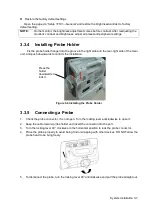
Page 29: ... the main unit and push downwards to confirm the installation Figure 3 4 Installing the Probe Holder 3 3 5 Connecting a Probe 1 Check the probe connector if is not open Turn the locking lever anticlockwise to open it 2 Keep the cable toward probe holder and insert the connector into the port 3 Turn the locking lever 90 clockwise in the horizontal position to lock the probe connector 4 Place the pr...

Page 30: ...n example insert the USB connector to the system available USB ports on the left and rear of the machine then the footswitch can be used directly 2 For settings of footswitch please refer to 3 5 3 system preset Figure 3 5 Footswitch connection 3 4 2 Video Printer Installation Analog video printer 1 Connect one end of the signal line to the Video In interface of the printer and the other to the vid...

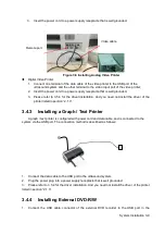
Page 31: ...ed not install the driver of the printer listed in section 2 1 3 3 4 3 Installing a Graph Text Printer A graph text printer is configured with power cord and data cable and is connected to the system via the USB port The connection method is described as follows 1 Connect the data cable to the USB port in the ultrasound system 2 Plug the power plug into a power supply receptacle that is well groun...

Page 32: ...r and make sure the ultrasound system and other optional devices are correctly connected When the AC indicator is green you can turn on the power button located at the upper right corner of the system to initiate the system After being normally rebooted it will display image interface Or press the power button directly when the battery is of sufficient capacity 3 5 2 Enter Doppler After the system...

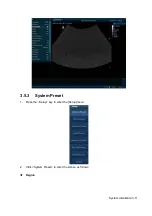
Page 33: ...System Installation 3 11 3 5 3 System Preset 1 Press the Setup key to enter the Setup menu 2 Click System Preset to enter the screen as follows Region ...

Page 34: ...egion page set the system language date format date time and hospital related information etc General Click System Preset to enter In this page set the time of standby brightness contrast and color temperature of display etc Key Config ...

Page 35: ... user defined 2 Key brightness key volume trackball backlight and trackball sensitivity can be adjusted Image Preset Click Image Preset to enter General image parameters can be set in this page 3 5 4 Print Preset 1 Press Setup and click Print Preset to set video printer graph text printer parameters ...

Page 36: ...turn Printer Service page Select the corresponding service from the printer list and increase the service The system integrates drivers of HP printers after HP printers are connected drivers will be installed automatically about 10s If auto installation fails icon will display on the right lower corner of the screen to warn you that manual installation is necessary The driver installation method i...

Page 37: ...n the newly added network printer name will be shown in the printer driver list NOTE 1 Before connect the network printer make sure the ultrasound system and the printer are in the same network domain and the network is working normally 2 The IP address and the server name should be valid e g 10 2 40 123 or 5 HP otherwise the system will fail to connect 3 If the server has set accessing limitation...

Page 38: ... basic option is configured DICOM Local DICOM Server DICOM Service are available 1 Click DICOM Preset to open the DICOM preset screen DICOM Setting Enter the AE Title of the ultrasound system port and PDU according to the actual situation and then click OK to exit the screen NOTE 1 AE Title should be the same with the SCU AE Title preset in the server PACS RIS HIS 2 DICOM communication port in the...

Page 39: ...m is configured with DICOM basic function module and installed DICOM Work list MPPS DICOM Structured Reporting and Query Retrieve modules can the corresponding preset settings be found in DICOM Service screen The DICOM Service Setting is used to set properties of DICOM services as Storage Print Work list MPPS Storage Commitment and Query Retrieve NOTE DICOM Work list can be configured only after D...

Page 40: ...heck the product information here 1 Press the Setup and click System Info 2 Click About Detail to check the detailed board information 3 Click Save to export the information in the format of TXT click Exit to return to the Setup menu NOTE 1 Be sure to confirm the system information before and after the software maintenance 2 Ask the user to save the current system information if necessary ...

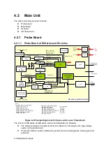
Page 41: ...wer supply Comm control Ultrasound signal CPU module 4D drive board Figure 4 1 Schematic Diagram of System As a portable black and white ultrasonic product the system supports two probe slots The detailed structure of hardware system is in the figure above and they can be divided into 4 modules Main unit module Power supply module Monitor module Control panel module The detailed description of 4 m...

Page 42: ...ROBE_A_SPI_DIN DATA0 PROBE_A_SPI_DOUT DP_SWITCH PROBE_A_SPI_nWP DATA1 PROBE_A_SPI_SEL Probe board control signal CTRL_PROBE_B_245_OE_N PRB_A_ON VDD A probe socket control signal VDD PRB_B_ON probe socket control signal Drive High voltage switch signal Drive Drive LDO D 3V3 A 5V A 95V A 95V 5V D 3V3 2 B probe socket control signal PROBE_B_SPI_CLK CLK PROBE_B_SPI_CS nLE PROBE_B_SPI_DIN DATA0 PROBE_B...

Page 43: ... main board Main board HVISO 32ch 64ch BF FPGA Control signal DATA DSP FPGA High voltage control signal IQ DDR2 UPLOAD DDR2 PCIE X1 CPLD control signal Rx9 16 Rx49 64 Or Rx25 32 Rx1 8 LVDS 8 Tx9 16 Tx49 64 Or Tx25 32 Tx1 8 Probe board PCIE PHY Comm control bus Control signal High voltage pulse output circuit Drive circuit Tx TGC 8 channel digital LNA VGA ADC Rx 8 channel analog Control signal Cont...

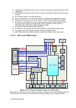
Page 44: ...communicates with the probe board via BF FPGA DSP FPGA controls the 4D drive board to output the 4D signal to the probe board 4 2 2 2 Back end of Main Board IO board PCIE PHY PCIE X1 SATA HDD VGA USB Video S Video Remote Ethernet MUL FPGA LPC LVDS USB CPU module SATA 12V LVDS Display SMBUS Control signal of the inverter Video Encoder Cont rol Data USB lateral USB System monitor circuit Power suppl...

Page 45: ...rd is to implement the ECG port on the IO panel The CPU module implements interfaces including USB Ethernet and VGA on the IO board System monitor circuit connects Multifunction FPGA though smbus Multifunction FPGA communicates with ARM by serial port to control transmission high voltage and also implements ARM update by serial port FPGA on the power supply module implements the machine power on o...

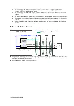
Page 46: ... CPU module output Status indicators of IO board respectively refers to12V 5V and 3 3V powers are normally working 4 2 4 4D Drive Board Main board Probe Connected Assembly Probe board 4D Drive Board Communication signal Power amplication Voltage control Motor driving signal 4D probe Hall return signal 12V Socket connection 4D probe Socket connection Communication Control Power supply Ultrasonic si...

Page 47: ...und System Monitor Ultrasound system monitor is mainly to monitor every voltage of interior machine and temperature Function On the back end of the main board a special monitor IC is used to monitor signal voltages and clock battery power that are provided to the main board by the main unit box power supply module The system temperature is detected in three positions BF FPGA CPU module and power s...

Page 48: ...the IO panel three are used for indicators of 12V 5V and 3 3V output on the DC DC power board the other one is used for reserved indicator There are five indicators on the control panel in which power on status indicator is below the power button AC power on status indicator control is output by the power management FPGA on the power module The hardware indicator control is output by CPU The statu...

Page 49: ...ich is adjusted by signal control switch and brightness of the IO board output Color temperature and Gamma correction data memory in parameter board used matches LCD so that the corresponding display effect shall be consistent Multifunction FPGA generates switch control signal which drives triode to control inverter to open or shut off high voltage output Multifunctional FPGA generates PWM signal ...

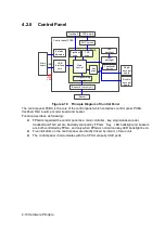
Page 50: ...Diagram of Control Panel The control panel PCBA is the core of the control panel which comprises control panel PCBA trackball TGC board encoder board and buzzer Function describes as following FPGA is regarded the control panel as a main controller key single dual encoder trackball and TGC ect are basically scanned by FPGA Key LED backlight and buzzers are both controlled by FPGA and only when FPG...

Page 51: ...igure 4 11 Block Diagram of Power System The power supply configuration of the system describes as following The power supply module can be divided into AC DC power board DC DC power board battery and battery connecting board High voltage programmable ARM and power management FPGA are on the DC DC power board Power output by the power supply module is transmitted to main board and then it is outpu...

Page 52: ...d high voltage switch 12 95V Probe board high voltage switch 13 PHV Transmitting high voltage 14 PHV Transmitting high voltage 4 3 2 System Power on Control CPU module PWR_BTN_N D12V SUS_S3_N SUS_S4_N CPU_PWR_BTN_N PWR_OK_N 5VSTB power supply manag ement FPGA AC DC board 19V AC in place signal DC DC board Main board Control panel PWR_12V_EN_N PWR_5VSTB_EN_N PWR_5VSTB_OK_N PWR_12V_OK_N AC_IN_STATUS...

Page 53: ...module which is used to control other power of the DC DC power board except 5VSTB and 3V3STB to be power on 7 PWR_5VSTB_EN The output of power management FPGA notifies power to provide 5V standby power 8 PWR_12V_OK_N Power status signal indicate 12V power has been provided steadily 9 PWR_5VSTB_OK_N Power status signal indicate 5VSTB power has been provided steadily When battery and AC supply the p...

Page 54: ..._OK_N is valid Power supply module CPU_PWR_BTN_N is valid Power management FPGA SUS_S3_N and SUS_S4_N is invalid CPU module PWR_12V_EN is valid Power management FPGA PWR_12V_OK_N is valid Power supply module CPU start up CPU module 12V and 5V start up DC DC power board PWR_OK_N is valid Power management FPGA YES Indicating 12V output of power module is normal Indicating 5VSTB_CPU output of power m...

Page 55: ...turned on no any abnormal noise appear in process 3 Check basic system information such as product configuration options software version etc Confirm all the information is normal 4 Check the preset of the monitor such as contrast and brightness 5 Check if the time and date are correct if not please preset them again 6 Check the log together with the user to confirm any abnormality or occasional a...

Page 56: ...e functions of all keys and knobs Follow the direction left to right and up to down All keys and knobs are effective Function checking of the trackball Press the Freeze key to enter the Freeze status Press Measure to enter into measure status do vertical and horizontal measurement or do other trackball operations The trackball can be rotated easily and smoothly the cursor responds sensitively the ...

Page 57: ... is black right 5 3 2 3 Check DVD Procedure Standard DVD R W Drive Check if connection is normal Press Eject button on the drive Perform DVD reading and writing The DVD R W driver can be ejected smoothly Data reading and writing performs normally without abnormal noise 5 3 2 4 Check Peripheral Device Procedure Standard Footswitch Connect the footswitch connection and check the functions of footswi...

Page 58: ...sted ECG signal can be reviewed correctly 5 3 2 6 Check IO Ports Procedure Standard Checking IO ports Video audio interface USB port have been verified remains are VGA port Connect VGA display Network port USB port The contents displayed on the VGA LCD are the same as those displayed on the ultrasound system display no character and image loss no color difference no fluttering and flicking Smooth ...

Page 59: ...the real time parameter values as follows Display F D G FR DR Image Parameters Frequency Depth Gain Frame Rate B Dynamic Range Parameters that can be adjusted to optimize the B Mode image are indicated in the following Adjustment Items Control Panel Gain Depth TGC iTouch Focus Frequency Menu Frequency Acoustic power Line Density ExFOV iClear H Scale Focus Position Focus Number Persistence iBeam Dy...

Page 60: ...n will change in correspondence with the knob rotates Frequency adjustment Press Focus Freq THI to light on the Freq THI indicator rotate the knob Rotate clockwise to increase Rotate anticlockwise to decrease FR will be changed relevantly iTouch Press Gain iTouch iTouch sign will be displayed in the image area to activate image effect auto optimization Click iTouch on the image menu to adjust gain...

Page 61: ...ensity and rotate the multifunction knob to adjust the parameter The higher the line density the higher the resolution and the lower the frame rate iClear B mode menu iClear Click iClear to adjust off represents no iClear is turned on and the bigger the value the stronger the effect The bigger the value the more clearly the profile of the image B mode menu U D Flip L R Flip B mode menu U D Flip L ...

Page 62: ...e tissue motion along with anatomical images of B Mode Press Update To switch between the active B image and frozen B image Tips a Adjustment of the depth focus position or TGC to the B Mode image will lead to corresponding changes in M Mode image b For details of other control panel adjusting parameters please refer to descriptions in B mode ...

Page 63: ...t of B Mode b Refer to B mode for more details 5 4 2 3 Color Mode In Color Mode scanning the image parameter area in the right corner of the screen will display the real time parameter values as follows Display F G WF PRF Image Parameters Frequency Color Gain Color Wall Filter Pulse Repetition Frequency Parameters that can be adjusted to optimize the Color Mode image are indicated in the following...

Page 64: ...Procedure Standard Press Freeze key to freeze an image and the Cine key indicator lights on The system automatically enters the manual cine status Precondition set Status after Freeze to be Cine Press iStation click Review or press Review to open the cine file Cine Review status To enter cine auto cine review status Roll the trackball Manual cine review Click image menu Auto Play Activate auto cin...

Page 65: ...n measurement functions are related to certain application software packages 5 4 2 7 Patient Information Management Procedure Standard Press Save1 2 in image scanning process preset already The image will be saved to corresponding patient database and the saving icon will be displayed in the right of the screen Press Review Click Exit on the Review screen or press Review or ESC To enter Review To ...

Page 66: ...ation environment 3 Scanning techniques contact the probe with the acoustic window of the phantom no spacing nor pressing Tips For the testing phantoms please refer to Appendix B 5 5 2 1 Resolution transverse resolution Test Step 1 Cover the scan surface of the phantom with water or couple gel gently contact the probe with the scan surface making the transverse resolution testing targets to be dis...

Page 67: ...er or couple gel gently contact the probe with the scan surface making the longitudinal resolution testing targets to be displayed around the midline of the image 2 Adjust the focus point focuses at the position where the longitudinal resolution testing targets are displayed 3 Adjust parameters like gain dynamic range TGC making the background tissue unseen just displaying the target image clearly...

Page 68: ...surface 2 Set the system display depth according to the expected maximum available depth of the probe in use 3 Adjust the focus point to the deepest and AP at the maximum value 4 Set gain contrast TGC at a greater value but no halation nor defocus is allowed 5 Record the depth of the furthest target the target can be seen clearly NOTE 1 Increasing the gain will also increase the noise and echo may...

Page 69: ...n the longitudinal targets line using the measurement caliper 3 Select the value with the greatest error to 20mm calculate the accuracy using the formula below NOTE 1 The measurement caliper should be positioned at the upper edge of the target not the middle nor the lower edge 2 The scanning plane should be vertical to the target line that means the scanning plane is parallel with the cross sectio...

Page 70: ... 4 Adjust parameters like gain TGC making each transverse targets to be clearly displayed 5 Record the distance by 20mm each segment on the transverse targets line by using the measurement caliper 6 Select the value with the greatest error to 20mm calculate the accuracy by using the formula below NOTE 1 When using a linear probe record the transverse distance by segment 2 When using a convex probe...

Page 71: ... the scan surface 3 Decrease the value of parameters like AP Gain until the background noise just can be seen 4 Record the smallest depth of the target that can be seen clearly that value is the blackout area value NOTE 1 When using a linear probe please completely contact the probe with the scan surface no side clearance is allowed 2 For convex probe the targets in the blackout area should be pos...

Page 72: ......

Page 73: ...re perform system maintenance To log on the system 1 When access control function has not been activated press Ctrl to show the Login dialogue box and then select the Service as the user name 2 When access control function has been activated already press Ctrl when the Login dialogue box is displayed and then select the Service as the user name 3 Press Setup key to open the Setup menu click Mainte...

Page 74: ...n Restoration Refer to recovery guide 6 3 Installation of Optional Devices 1 Copy the optional devices to the U disk then insert it to the USB port of the ultrasound system 2 Enter Preset click Maintenance to enter Option menu to select the option module to be installed ...

Page 75: ...he corresponding function is activated after returning from preset Note After all modules are installed please go to the previous interface to confirm Trial select the corresponding software package and then click Trial Note for each component you can activate trial version only once The trial lasts 180 days for each key Promote 1 Click Promote The following image appears ...

Page 76: ...ct the key to be promoted 3 Click OK to complete the promotion Note it is unavailable to use promotion for multiple optional keys For the optional key which is promoted it can also be installed The promotion lasts 365 days for each key Uninstalling 1 Select the software package to be uninstalled from option list 2 Click Uninstall and it pops up the Confirm dialogue box Click OK ...

Page 77: ...ttings Press Setup to open the Setup menu click Other to open the Manage Setting interface System preset can be performed here Image parameters can be exported imported or restored to factory Note The uninstalling function is exclusive to internal users The service engineers must log in the system with the account of Service and then conduct the uninstallation ...

Page 78: ...e factory setting but the Region Admin Network Preset and DICOM Preset cannot be restored 6 4 2 Patient Data Backup and Restore 6 4 2 1 Patient Data Backup 1 Press iStation on the control panel to open the iStation dialogue box 2 Click Select All to select all the data or select the target data one by one 3 Select the data click Backup to pop up the Backup patient Record dialogue box select the ta...

Page 79: ...d load the file in the popped up dialogue box 3 Select correct file PCF format and click OK After the operation is completed the successful prompt appears Restart the machine according to the prompt Specific configuration a Model configuration b Customized product logo hospital logo screen saver hibernation icon active inactive icon of dual B mode system information boot up shut down graphics NOTE...

Page 80: ...rage device only make sure the connection between U disk and ultrasound is normal before the exporting 6 5 2 2 Log Uploading 1 Click Upload Log on the Maintenance menu and select the log type in the sub menu 2 Click Upload in the popping up dialogue the system performs log uploading automatically After the uploading is finished the system will prompt Upload succeed If uploading is failure or can t...

Page 81: ...play Parameter Setting NOTE In normal condition when changing display assembly or main board assembly the hardware will update the display data automatically If synchronization fails please load display parameters manually to assure image effect 1 Log in as Service user 2 Enter Maintenance menu in Setup menu Then select Test Main Monitor to enter 3 Click the upper icon in the screen prompts Update...

Page 82: ...tion is as follows Blocks G system Notes 10 Linux C 441 7 Linux D 10 Linux E 1 C drive Catalog Data Illustration C z6 Image POD Probe data supported probes in the system ColorSpectrum map data color scale and colorize gui Font font file Skin Skin file pinyinmap pinyin data Word input setting data LayoutInfo Layout configuration file version txt Version file app bodymark pictogram DCM structured re...

Page 83: ...ersion file config Boot_logo png Doppler boot up graphics Hospital logo bmp Hospital logo manu_logo png Manufacturer logo Real_Image bmp Active icon Non_Real_Image bmp Inactive icon Dorm_logo bmp Standby graphics Product PCF Product configuration file Key Factory key Factory key file 2 D drive Catalog Data Illustration D z6 gui word User defined word library log DcmLog DICOM log Monitor Monitor lo...

Page 84: ...e Preset Current User preset data temporary Temporary file PatientBack Patient back up data 3 E drive Catalog Data Illustration E z6 Demo Ivision default DEMO path Patient Backup Patient data back up demofile txt Ivision default DEMO path ...

Page 85: ... of the Complete System Figure 7 1 Overall Exploded View No Name No Name 1 Holder 5 Null turning axis of keyboard 2 Rear cover assembly of main unit 6 Silicon cap of keyboard 3 Assembly of main unit rack 7 Top cover assembly of keyboard 4 Display assembly 8 Bottom cover assembly of keyboard ...

Page 86: ...1629 03 Z6 Z8 Series Used for Z6 Z8 and Z6Vet of any Doppler software version Refer to7 4 5 2 Mainboard FRU No spread spectrum chip 115 031629 04 Z6 Z8 Series Used for Z6 Z8 and Z6Vet with Doppler software version V02 01 00 or above After replacement restore the Doppler software to version V4 3 1 for human use V5 1 1 for vet use or above If the machine s Doppler software version is former than V02...

Page 87: ... PC Module CPU Module with 115 043600 00 has been discontinued If it is out of stock please use 115 043600 01 to order and restore the latest Doppler software and compatible OS as well after replacement Refer to7 4 5 BayTrail PC Module 1112 1114 FRU 115 043600 01 Z6 Z8 Series BayTrail PC Module CPU Module with 115 043600 00 has been discontinued If it is out of stock please use 115 043600 01 to or...

Page 88: ...in unit related 4D Module Kit 115 044346 00 Z6 Z8 Series Z8 Platform this board should be used with software of version V04 00 00and later Refer to7 4 5 5 Main unit related HDD 115 044352 00 Z6 Z8 Series CE HDD Assembly Z8 CE FRU Refer to 7 4 8 115 044354 00 HDD Assembly Z8 Pro CE FRU 115 044356 00 HDD Assembly Z8 Expert CE FRU 115 044357 00 HDD Assembly Z8S CE FRU 115 018454 03 HDD Assembly Z6 CE...

Page 89: ...pert CE FRU 115 044360 00 HDD Assembly Z6S CE FRU 115 044361 00 HDD Assembly Z6T CE FRU 115 044362 00 HDD Assembly Z6W CE FRU 115 018455 03 HDD Assembly Z6Vet CE FRU for V4 0 to V5 0 115 018455 04 HDD Assembly Z6Vet CE FRU for V5 0 or above 6 Main unit related HDD 115 018452 03 Z6 Z8 Series FDA HDD Assembly Z6 FDA FRU Z8 Platform Refer to 7 4 8 115 018453 03 HDD Assembly Z6Vet FDA FRU for V4 0 to ...

Page 90: ...isassembl y 115 018453 04 HDD Assembly Z6Vet FDA FRU for V5 0 or above 7 Main unit related Battery connecting board 801 1150 00004 0 0 Z6 Z8 Series Refer to7 4 1 8 Main unit related IO Board Z8 FRU 115 044349 00 Z6 Z8 Series Z8 Platform this board should be used with software of version V04 00 00and later Refer to7 4 3 ...

Page 91: ... Model Compatibility Assembly Disassembl y 9 Main unit related Probe Board Assembly Z8 FRU 115 044347 00 Z6 Z8 Series Z8 Platform Refer to7 4 4 10 Power related power supply module 801 1150 00009 0 0 Z6 Z8 Series Refer to 7 4 2 11 AC DC board FRU 115 051844 00 Z6 Z8 Series Refer to 7 4 2 ...

Page 92: ...ription Photo Order Number Model Compatibility Assembly Disassembl y 12 DC DC board FRU 115 051845 00 Z6 Z8 Series Refer to 7 4 2 13 Battery CE 115 011471 00 Z6 Z8 Series CE For CE Refer to7 4 1 14 Battery FDA 115 011472 00 Z6 Z8 Series FDA For FDA Refer to7 4 1 ...

Page 93: ...ssembl y 15 Top Cover of Keyboard Assembly Z8 FRU 115 044348 00 Z6 Z8 Series Z8 Platform this board should be used with software of version V04 00 00and later Refer to7 4 6 5 16 Control Panel Cover Z8 FRU 115 044386 00 Z6 Z8 Series Z8 Platform Refer to7 4 6 5 17 Silicon Keypad Z8 FRU 115 044387 00 Z6 Z8 Series Z8 Platform ...

Page 94: ...assembl y 18 Double encoder 801 1150 00013 0 0 Z6 Z8 Series Refer to Focus Freq and Depth Zoom Refer to7 4 6 1 19 Single encoder 801 1150 00014 0 0 Z6 Z8 Series Refer to Gain or Nav Rot Refer to7 4 6 1 20 Trackball 801 1150 00015 0 0 Z6 Z8 Series Refer to7 4 6 2 21 TGC board 801 1150 00016 0 0 Z6 Z8 Series Refer to7 4 6 3 ...

Page 95: ...el Compatibility Assembly Disassembl y 22 Monitor related 1150 Display assembly 115 045050 00 Z6 Z8 Series Refer to7 4 7 23 Others Backboard fan 024 000147 00 Z6 Z8 Series Refer to7 4 5 24 Power fan 024 000146 00 Z6 Z8 Series Refer to7 4 2 1 25 Speaker 115 045172 00 Z6 Z8 Series Refer to7 4 9 ...

Page 96: ...bl y 26 ECG Module AHA lead CE Z6Vet 115 050430 00 Only for maintenance 27 ECG Module IEC lead CE Z6Vet 115 050431 00 Only for maintenance 28 ECG Module AHA lead FDA Z6Vet 115 050517 00 Only for maintenance 29 ECG Module AHA lead CE 115 044646 00 Only for maintenance 30 ECG Module IEC lead CE 115 044647 00 Only for maintenance ...

Page 97: ...disassembling of ultrasound equipment 1 When you stop the scanning and the image capture you should power off the system and disconnect the system from the AC power supply then pull out AC power cables 2 Open the battery cover and removing battery 3 Prepare Tools disassembled and anti static gloves WARNING Please start to disassemble when you are sure that you have pull battery out 7 4 Assembly Di...

Page 98: ...CPU module Main board Note 1 The up to down arrows indicate the assembly disassembly sequence 2 The box with the same content format indicates independent assembly Battery connecting board 7 4 1 Battery Connecting Board 1 Press the clasp of the battery cover and then rotate the battery cover down to open it Figure 7 2 Disassembly of Battery 1 2 Slide battery to the left side pressing it all the ti...

Page 99: ...rews with washers 5 M3X8 and 2 M3X12 which are installed on the rack of the main unit rear cover Figure 7 4 Disassembly of Rear Cover Assembly of Main Unit 1 4 Hold the battery bay and then remove the rear cover of the main unit simultaneously pull out the plugs from the battery connecting board ...

Page 100: ...ain unit referring to 7 4 1 the 1 4 step 2 Remove panhead screws with washers 4 M3X6 fixed on the main unit box Figure 7 7 Removing the power shielding box 3 Then take off the power shielding box Pull out the plug of the battery connecting board cables on the power module assembly 4 After removing panhead screws with washers 6 M3X6 fixed on the main unit box and one panhead combination screw M4X8 ...

Page 101: ...6 fixed on the power module assembly and pulling out the plug of the fan connecting cables and power input outlet connecting cables you can take off the rear panel of power supply assembly Figure 7 10 Disassemble the rear panel of power supply assembly 1 Figure 7 11 Disassemble the rear panel of power supply assembly 2 2 Remove the 4 screws fixed on the fan and then take out the fan on the rear bo...

Page 102: ...ard Figure 7 13 Disassemble the DC DC Power Board 1 2 Remove the plug of fan cable Figure 7 14 Disassemble the DC DC Power Board 2 3 After removing the connecting plug between DC DC power board and AC DC power board you could take out the DC DC power board NOTE During the assembly fan label must be pasted towards the surface of the machine and don t confuse with fans of other products ...

Page 103: ...C power board and AC DC power board you could take out the AC DC power board Figure 7 17 Disassemble the AC DC Power Board 2 7 4 3 IO Broad 1 Remove rear cover assembly of the main unit referring to 7 4 1 the 1 4 step 2 Pull out the connecting cable plug on the IO board assembly 3 Remove panhead screws with washers 6 M3X6 which are fixed on the rack of the main unit at the back of the main unit an...

Page 104: ... Probe Board 1 Remove rear cover assembly of the main unit referring to 7 4 1 the 1 4 step 2 After removing panhead screws with washers 13 M3X6 which are installed on the rack of the main unit rear cover and cutting off cable ties fixed on the probe board you could remove the probe board assembly backward Figure 7 20 Disassemble the Probe Board Assembly NOTE Make sure that you could pull out and p...

Page 105: ... out the power shielding board and then pull out two cables connecting the main board to the power module assembly Figure 7 22 Disassemble the Main Board Assembly 1 3 Remove the probe board assembly referring to 7 4 4 the 2nd step and the IO assembly referring to 7 4 3the 1 4 step 4 Remove panhead screws with washers 8 M3X6 fixed on the main unit box and take out separating board assembly of the m...

Page 106: ...xed on the main unit box you can take off the board Remove the HDD in back of the board the left is main board Figure 7 25 Disassemble the Main Board NOTE 1 You can t draw out the CPU module abruptly but you would pull it out after loosening the board from the left right side to avoid damaging the main board FPGA 2 After replacing the CPU module key file must be generated once again according to t...

Page 107: ...tter versions 7 4 6 Top Cover Assembly of Keyboard 1 Remove plugs fixed on the on the top cover of keyboard 4 for each and take off the corresponding panhead screws with washers M3X8 4 for each Figure 7 26 Disassemble the Top Cover of Keyboard 1 2 Hold the upper edge of the keyboard upper cover assembly and open up the keyboard upper cover to the extent till you can remove the screw for fixing the...

Page 108: ...ncoder Board 1 Draw out the 4 knobs upwards fixed on the encoder board on the control panel assembly Figure 7 29 Disassemble the Encoder Board 1 2 After removing the connecting cable plug on the control panel and taking out countersunk head self tapping screw PT3X10 7 used to secure the encoder board you could remove the encoder board Figure 7 30 Disassemble the Encoder Board 2 7 4 6 2 Trackball R...

Page 109: ...igure 7 32 Disassembly of the TGC Board 1 2 After removing the connecting cable plug of TGC board and removing screws PT3X10 4 fixed on the TGC board you could remove the TGC board Figure 7 33 Disassembly of the TGC Board 2 7 4 6 4 Buzzer After removing the connecting cable plug of buzzer on the control panel and taking out the buzzer fixing screw PT2X8 2 you could remove the buzzer ...

Page 110: ...35 Disassemble the Control Panel 1 2 Remove the encoder board TGC board and trackball The remained part is top cover assembly of keyboard basic 3 Remove the buzzer and then remove 18 PT3X10 self tapping screws fixed on the control panel Figure 7 36 Disassemble the Control Panel 2 4 Pull out the control panel and silicon key from the keyboard cover and then dispatch them apart you can take out the ...

Page 111: ...ferring to 7 4 1 the 1 4 step 2 Remove combination screws 6 M3X8 used to be secured the monitor on the front cover of the main unit by a screwdriver Figure 7 38 Screws on the Right of the Display Assembly Figure 7 39 Screws on the Left of the Display Assembly 3 Cut off cable ties connecting the main unit on the display by diagonal cutting pliers and then ...

Page 112: ...wards to make it separated from the main unit Figure 7 41 View of Display Assembly 7 4 7 1 Backlight Inverter Board 1 Remove combination screws 4 M3X8 used to be secured the display on the front cover of the main unit by a screwdriver Figure 7 42 Disassembly of Display Front Cover 1 2 Tilt the frontal rear cover of the monitor assembly by external force ...

Page 113: ...nd removing connecting cables of the inverter board and backlight extension cables from the inverter board you could take out the inverter board Figure 7 44 Disassemble the Backlight Inverter Board of Display 7 4 7 2 LCD Screen 1 Remove combination screws 4 M3X8 used to be fastened the LCD screen Figure 7 45 Disassemble the LCD Screen 1 2 Remove EEPOM connecting cable ...

Page 114: ...CD signal cable 4 After removing combination screws M3X4 each for 2 used to fix the supporting assembly of display on the left and right you can pull out the LCD screen Figure 7 47 Disassemble the Monitor Assembly 3 5 When installing please attach the plug of backlight extension cables to the inverter board socket Figure 7 48 View of Connecting backlight Extension Cable and Inverter Board ...

Page 115: ... about 2 3 rings to confirm that the screw is fixed then pull out the monitor simultaneously rotate the display assembly to adjust the monitor to the horizon position Figure 7 49 Disassembly of HDD 1 2 Remove panhead screws with washers 5 M3X8 which are installed on the rack of the main unit front cover then remove the HDD cover assembly including HDD cover HDD cover metal part and conductive foam...

Page 116: ... of the main unit referring to 7 4 1 the 1 4 step 2 Remove 4 panhead screws with washers M3X6 used to fix the handle then take out the handle Figure 7 52 Disassembly of Speaker 1 3 Remove 1 combination screw used to fix the connecting cable of display assembly Cut off two cable ties and pull out the plug of connecting cable of display 4 Remove 1 combination screw used to fix the connecting cable o...

Page 117: ...gure 7 54 Disassembly of Speaker 3 6 Remove 5 panhead screws with washers M3X8 used to fix the front cover and HDD cover and then take the HDD cover assembly Figure 7 55 Disassembly of Speaker 4 7 Put the machine on the horizontal position remove 3 panhead screws with washers M3X8 which are fixed on the rack of the main unit at the bottom of the main unit take out the main unit rack assembly HDD c...

Page 118: ...nd then take out the speaker assembly 图 7 57 Disassembly of Speaker 6 10 As shown by arrow in the figure extrude the buckle of spring screw as shown in red circle inward take the pressing board of speaker first then you can remove the reducing libration mat 图 7 58 Disassembly of Speaker 7 11 As shown by arrow in the figure extrude the buckle of spring screw as shown in red circle inward remove 4 s...

Page 119: ...Structure and Assembly Disassembly 7 35 图 7 59 Disassembly of Speaker 8 ...

Page 120: ......

Page 121: ... indicator is green 4 When the battery capacity is less than 20 in discharging status the orange indicator blinks When less than 10 the orange indicator blinks quickly 5 When the battery is in non charging discharging status or no battery is in the indicator is not on The Control Panel on the lower left corner AC indicator The indicator is green when the system is connected to the AC power supply ...

Page 122: ...orange Entering or exiting the freezing status by the Freeze key Standby status There are 3V3 STB and 5V_STB of power are normal other power are off The standby indicator blinks orange 1 Press the power switch for a short time and then the system enters into the standby status by choosing from the status popped on the screen 2 If there is no operation for the time set at first the system would ent...

Page 123: ...ort time 8 2 Starting Process of the Whole System The system is powered on User screen Press the power button on the control panel Blank screen in the short time BIOS startup graphics displays Linux startup graphics displays no progress bar Doppler startup graphics displays progress bar displays Linux OS startup Doppler startup After the system is powered on BIOS startup Power on status indicator ...

Page 124: ...ter finishing HDD initialization and logic configuration PC enters into BIOS stage There are data output and images displaying on the monitor 8 2 1 2 Powered on by Battery Basic Procedures Phenomenon The original status finishing loading 3 3VSTB no indication Finishing loading 5VSTB The battery indicator on the control panel lights on but the indicators of HDD standby and AC status are off The pow...

Page 125: ... core loading The course of users logging on Start DOPPLER gather the following information system firmware information bus adapter type video card adapter type keyboard communication port thus to finish data inspection Function Loading the kernel and the hardware abstraction layer to the kernel Loading the controller information loading device driver programmer and service load dialogue managemen...

Page 126: ...ription Linux APP initialization There is no progress bar on the screen The progress bar does not appear unit in increments of 7 PC hard disk initialization There is no progress bar on the screen The PC software initialization Peripheral initialization There is no progress bar on the screen Platform initialization There is no progress bar on the screen GUI initialization There is progress bar appe...

Page 127: ...tialize the time and the processing function of Multilanguage Initialize peripheral file system network and the driver Enumerate peripheral ports Configure timer Initialize soft interruption construct maintenance servicer and configure static data of the system Configure system font Load layout information Initialize UI management and Initialize UI mark standard library In increments of 7 Initiali...

Page 128: ...ng management Initialize video replay device In increment of 1 Initializing ultrasound image Set the virtual machine device and initialize the virtual machine Construct object trees of the front end and the back end ultras and so on In increments of 2 Initializing ultrasound application Add function package of measure menu Register the application interface of measure patient In increments of 1 In...

Page 129: ... and LLL HHH represents the lower and upper limits The voltage names respectively are AD 12V A 12V A 5V AD 2V5 AD 1V8 D 1V5 D 1V2 Short circuited protection and overvoltage Check the related circuit Alarming tips LOG record Suggestion Temperature alarming XX Shut down XX means inversion timing starting 60S System Monitor Temperature Alert XXX Current voltage VVV degree Limit temperature LLL HHH de...

Page 130: ...ion is abnormal Battery I2C error Check the battery connection or replace battery Battery communication is abnormal please connect to AC power supply or shut down Otherwise the system shuts down automatically after 60s Battery I2C error the battery supply Check the battery connection or replace battery Battery temperature is too high please connect to AC power supply or shut down Otherwise the sys...

Page 131: ...is XX upper limit is XX Something is wrong with the programmed voltage of power module which make either of the both PHV circuits or multi path voltage 1 1 times more than the upper limit of voltage 100 AP none PHV protect PHV1P is XX PHV1N is XX PHV protection and the voltage of PHV is less than the lower limit 95V Power supply voltage error the voltage is XX normal region is 90V to 100V Somethin...

Page 132: ......

Page 133: ...e two probes Soft brush 1 pcs About a toothbrush size Small plastic basin 1 pcs Used to fill the soapy water Safety test analyzer 1 pcs Refer to appendix A Inner hexagon wrench 2 pcs Inner hexagon wrench 6 Table 9 2 Consumable List Consumable Qty Remarks Aluminum foil About 1 meter Physiological saline About 1000ml Filling a half container Immerging the whole probe referring to appendix A concentr...

Page 134: ...rface of connector Monthly Same as the above 6 Clean holders including probe holder and gel holder Monthly Same as the above 7 Clean cover Monthly Same as the above 8 Clean peripherals Monthly Referring to 9 2 2 9 Check surface of probe Daily Referring to 9 3 1 10 Check power cable and plug Monthly Same as the above 11 Check battery Annually Same as the above 12 Check function of peripherals and o...

Page 135: ...ng the system be sure to turn off the power and disconnect the power cord from the outlet If you clean the system while the power is On it may result in electric shock 9 2 2 Content 1 Clean Display Tool soft dry cloth clear water or mild soapy water Method Surface of display should be cleaned with soft dry cloth Remained stain should be washed out by cloth with clear water or soapy water and then ...

Page 136: ...ving the ring and the trackball wipe down the lens with a clean paper until you can see nothing in the groove zoom and then clean the other contaminant material please pay attention to your intensity adopted on wiping dust of bead down as shown in the following figure Power off is not need during cleaning and maintenance effect can be experienced directly After cleaning completely you can install ...

Page 137: ... b Remained stain or dust attached to surface of probe cable should be washed out by cloth with clear water or soapy water and then air dry the surface of probe cable c Use a soft brush to clean the probe holder removing dust simultaneously 5 Clean Holders Tools mild soapy water dry soft cloth Method a Wipe out the dust attached to surface or inner of probe holder b Remained stain or dust attached...

Page 138: ...eaning maintenance according to the operation manual if is necessary 3 Foot switch Use soft dry cloth with a little mild soap water to wipe off the dust or stain attached to the pedals or cable of foot switch 9 3 Checking 9 3 1 General check Table 9 5 General check list No Content Method 1 Probe a Visually check to confirm that there is no crack and expansion to probe head b Visually check to conf...

Page 139: ...operation of B mode Check basic software and hardware controls affecting B mode operations 2 Color mode Verify basic operation of Color mode Check basic software and hardware controls affecting Color mode operations 3 Doppler mode PW CW Verify basic operation of Doppler mode Check basic software and hardware controls affecting Doppler mode operations 4 M mode Verify basic operation of M mode Check...

Page 140: ...ICOM can work normally and send pictures and other data to DICOM server Remark Please refer to 5 3 for details 9 3 4 Mechanical Safety Inspection Mechanical safety inspection is mainly used to check mechanical strength and mechanical function of the key assembly of ultrasonic system The mode of test evaluation mainly is Perform the evaluation by means of visual check and operating check if the che...

Page 141: ... looseness and it can accept normal force none 4 Control panel and turning mechanism Open the control panel to confirm that turning mechanism is normal and the control panel is free of skewness and looseness none 5 Display and turning mechanism a Visually check to confirm there is no any crack to the cover of display b Manually operate the monitor to make sure that the turning angle of display is ...

Page 142: ......

Page 143: ...f the power button 3 Three Power indicators 12V 5V 3 3V located on IO board 10 1 3 Troubleshooting No Fault Description Cause Analysis Measure 1 Fail to start up when powered by the battery only but can start up normally by AC power supply After the machine is powered on battery alarm appears Internal battery fails Related board or module of the other power system is in normal status Replace batte...

Page 144: ...supply module fails Replace power supply module 10 2 System Cannot Start up Normally 10 2 1 Module or Board Related No Descriptions Remarks 1 CPU module 2 HDD 10 2 2 Key Points Supporting Troubleshooting No Key Points Supporting Troubleshooting Remarks 1 Character and progress status during the starting of the system 2 Alarm and prompts during the starting of the system 3 Backlight status during p...

Page 145: ... First restore the system or else replace the hard disk 5 LINUX start up graphics displays Blank screen with a cursor can response to control panel input Fail to load the Doppler software the HDD or OS in HDD may be damaged First restore the system or else replace the hard disk 6 Doppler software start up graphics displays but cannot continue Fail to load the Doppler software the HDD or OS in HDD ...

Page 146: ... etc Confirm by connecting another probe Replace the probe If several similar dark strips appear in the image Replace the main board or probe board If dark strips appear also after changing the probe socket dark strips disappear or change the place Replace the probe board 3 Noise appears in B image Probe malfunction e g array rear board air bubbles and cable shielding etc Confirm by connecting ano...

Page 147: ... Supporting Troubleshooting No Key Points Supporting Troubleshooting Remarks 1 Probe recognition of all models of probes when connecting on the same or different ports 2 Probe board ID of the system 10 4 3 Troubleshooting No Fault Description Cause Analysis Measure 1 Probe cannot be recognized This probe cannot be recognized by connecting to all probe sockets while recognition of other probes is n...

Page 148: ... printer Check if output of connected video printer is normal 10 5 3 Troubleshooting No Fault Description Cause Analysis Measure 1 LCD displays normally NO video printer output when press print on control panel Remote printing control failure or video output failure if there is no user defined key failure Replace the main board 2 Two speakers have no sound Main board malfunction Replace the main b...

Page 149: ...o trackball operation 5 Response to the sliding potentiometer To confirm if a single sliding potentiometer or the control panel PCBA is damaged 6 Response to each encoder To confirm if a single encoder or the control panel PCBA is damaged 7 Buzzer alarm The buzzer alarms when a key is blocked for 100 seconds 10 6 3 Troubleshooting No Fault Description Cause Analysis Measure 1 Buzzer alarms Key blo...

Page 150: ...ns Remarks 1 Monitor assembly Failure rate low 2 IO board Failure rate low 3 Main board 4 CPU module 10 7 2 Key Points Supporting Troubleshooting No Key Points Supporting Troubleshooting Remarks 1 Backlight of the LCD More obvious in dark 2 VGA output port on IO board Need external LCD 3 Display mode of the LCD Blank screen or No Signal displayed or disordered screen etc 10 7 3 Troubleshooting No ...

Page 151: ...lay blank screen on the LCD with backlight only or disordered screen monitor malfunction board or monitor assembly 3 Control panel powered on normally and no key indicator turns on orange No Signal displays on LCD No display external LCD connecting by VGA CPU module malfunction Replace CPU module ...

Page 152: ......

Page 153: ...alyzer test equipment These procedures assume the use of a 601PROXL International Safety Analyzer or equivalent safety analyzer Other popular testers complying with IEC 60601 1 used in Europe such as Fluke Metron or Gerb may require modifications to the procedure Follow the instructions of the analyzer manufacturer The consistent use of a safety analyzer as a routine step in closing a repair or up...

Page 154: ...amage to the plug body The Strain Relief No physical damage to the strain relief No plug warmth for device in use The Power Plug No loose connections The Power Cord The Power Cord No physical damage to the cord No deterioration to the cord For devices with detachable power cords inspect the connection at the device For devices with non detachable power cords inspect the strain relief at the device...

Page 155: ...switches connectors etc No residue of fluid spillage e g water coffee chemicals etc No physical damage to probe surface e g crack etc No loose or missing parts e g knobs dials terminals etc Contextual Inspection The Enclosure and Accessories No unusual noises e g a rattle inside the case No unusual smells e g burning or smoky smells particularly from ventilation holes No taped notes that may sugge...

Page 156: ... SAFETY INSPECTION 3 Device Labeling TEST PROCEDURE Check the labels provided by the manufacturer or the healthcare facility is present and legible Main Unit Label Integrated Warning Labels Slope and High Voltage Caution Label Don t Stress Label ...

Page 157: ...ssing AMPERES SOFT KEY 3 2 Connect the test lead s between the RED input jack and the GREEN input jack 3 Press CAL LEADS The 601PRO will measure the lead resistance and if less than 0 150 Ohms it will store the reading and subtract it from all earth resistance readings taken at the calibrated current 4 If the calibration fails the previously stored readings will be used until a passing calibration...

Page 158: ...seconds 6 Press the print data key at any time to generate a printout of the latest measurement s Note When Over is displayed for Ohms this signifies that a valid measurement was not obtained because either an open connection was detected or that the measurement was not within range Readings greater than 9 999 Ohms will be displayed as Over Failure Once it reaches the limitation stop using equipme...

Page 159: ...s the measuring device internally TEST PROCEDURE Perform the Test 1 From the MAIN MENU or with the outlet unpowered plug the DUT into the 601PRO front panel outlet and turn on the device 2 Attach the device s applied parts to the 601PRO applied part terminals if applicable 3 Press shortcut key 4 The Earth Leakage test appears on the display and the test begins immediately SOFT KEY 1 toggles the DU...

Page 160: ... or owner to correct any deviations As a work around check the other outlets to see if they could be used instead Change another probe to confirm if the fail is caused by console Inspect mains wiring for bad crimps poor connections or damage If the leakage current measurement tests fail on a new unit and if situation can not be corrected submit a Safety Failure Report to document the system proble...

Page 161: ...ng If all of the applied parts correspond to the instrument type the applied parts will be tied together and one reading will be taken If any of the applied parts differ from the instrument type all applied parts will be tested individually based on the type of applied part This applies to Auto and Step modes only Perform the Test 1 From the MAIN MENU or with the outlet unpowered plug the DUT into...

Page 162: ...tive one Check any broken of the ECG PCG module if used Replace any defective one Check any broken of the Power Unit Replace a new one if any portion defective Inspect wiring for bad crimps poor connections or damage Test the wall outlet verify it is grounded and is free of other wiring abnormalities Notify the user or owner to correct any deviations As a work around check the other outlets to see...

Page 163: ...Electrical Safety Inspection A 11 ELECTRICAL SAFETY INSPECTION 6 Patient Leakage Current LIMITS All countries For BF ECG input and transducer 100μA Normal Condition 500μA Single Fault Condition ...

Page 164: ...eversed Polarity TEST PROCEDURE Prepare To perform a calibration from the Mains on Applied Part test press CAL SOFT KEY 2 1 Disconnect ALL patient leads test leads and DUT outlet connections 2 Press CAL to begin calibration as shown If the calibration fails the previously stored readings will be used until a passing calibration has occurred Also the esc stop key has no effect during calibration 3 ...

Page 165: ...ld be perform if ECG or PCG parts used 2 If all of the applied parts correspond to the instrument type the applied parts will be tied together and one reading will be taken If any of the applied parts differ from the instrument type all applied parts will be tested individually based on the type of applied part This applies to Auto and Step modes only Failure Check any broken of the Applied part R...

Page 166: ... wiring for bad crimps poor connections or damage If the leakage current measurement tests fail on a new unit and if situation cannot be corrected submit a Safety Failure Report to document the system problem Remove unit from operation If all else fails stop using and inform the Customer Service Engineer for analysis and disposal LIMITS All countries For BF ECG input and transducer 5000μA ...

Page 167: ...ice Enclosure and Accessories 3 Device Labeling 4 Protective Earth Resistance Ω Max 0 2 Ω 5 Earth Leakage Normal condition NC ____μA Max NC 300μA refer to UL60601 1 NC 500μA refer to IEC60601 1 SFC 1000μA Single Fault condition SFC ____μA 6 Patient Leakage Current Normal condition NC BF____μA Max BF applied part NC 100μA SFC 500μA Single Fault condition SFC BF____μA 7 Mains on Applied Part Leakage...

Page 168: ......

Page 169: ...t group B Blind area target group C Longitudinal target group D Horizontal target group E Mimic tumor F Mimic sac diam 10mm and stone G Mimic sac diam 6mm 4 Line Target System There are 8 groups of nylon line targets disposed as shown in the figure 1 A1 A5 Axial and lateral resolution target group The distances between the horizontal branch and the acoustic window are 30 50 70 120 and 160mm the ce...

Page 170: ...xial resolution target group The upmost lines in each target locate at the depth of 10 30 50 70mm the center longitudinal distances of each group from the top down are 3 2 1 0 5mm and the horizontal distance is 1mm 2 B1 B4 Lateral resolution target group Locate at a depth of 10 30 50 70mm with a center horizontal distance of 4 3 2 1mm in each group 3 C Longitudinal target group 12 target lines wit...

Page 171: ...Phantom Usage Illustration B 3 ...

Page 172: ......

Page 173: ...P N 046 010452 00 5 0 ...

Reviews: