Troubleshooting Guidelines
Repair Information
3 - 2
3.3
Troubleshooting Guidelines
1. Identify the problem
Due to the wide variety of potential symptoms, certain problems may be more subtle
than others. One approach to troubleshooting is to set up the instrument as described in
Chapter 5.0. Following the guidelines of the tests will help determine the problem if one
exists.
2. Avoid shorting component leads
During repair procedures, it can become tempting to make a series of quick
measurements. Always turn the power off before connecting and disconnecting the test
leads and probes. The accidental shorting of leads can easily stress the components and
cause a second failure (aside from the safety risk).
3. Use the Proper equipment
The equipment listed below is suggested to fulfill a wide range of troubleshooting
requirements. It is imperative to use the designated equipment in order to ensure proper
results of any and all test procedures.
4. Clean up the repair area
After any repair, especially after any soldering or desoldering, clean off the repair area
with alcohol and a stiff brush. This will remove any residual solder flux, in turn allowing
the instrument to return to its original appearance.
3.4
Special Tools Required
• Digital Voltmeter
• Digital Mercury Manometer – 0 to 300 mmHg
• Safety Analyzer
• Patient Simulator
• Test Chamber / Dummy Cuff (P/N 0138-00-0001-01 (700 cc) or -03 (500 cc))
• Desktop PC or notebook PC.
• Microsoft Windows 2000/XP operating system
• Intel Pentium CPU, above 500MHz
• Above 128M memory
• At least one network card and at least one USB port
• CAT-5 crossover cable
• USB cable or DPM SB storage device
3.5
Disassembly Instructions
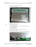
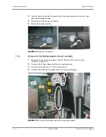
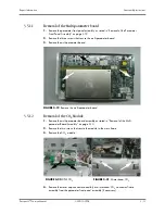
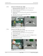
Before disassembling the unit, perform the following:
• Power down the unit and remove the line cord.
• Remove all cable assemblies from the left side, right side, and rear of the unit.
• Remove any batteries that were installed.
• Perform all work on a properly grounded ESD workstation.


