background image

Passport V™ Service Manual

0070-10-0705

3 - 39

Repair Information

Troubleshooting Menus

3.16.2

NIBP Troubleshooting

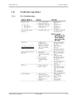
ECG Channels Checking...

1

Appears when the ECG 

Module is calibrating.

1

This is normal operation. 

Turn off ECG module 

calibration and the 

message will be cleared.

Initialization Error

1

During the ECG module 

power-on, as the ECG 

module communication 

stops, system fails to 

communicate with 

module.

1

Contact Technical 

Support.

MESSAGE/PROBLEM

REASON

SOLUTION

MESSAGE/ PROBLEM

REASON

SOLUTION

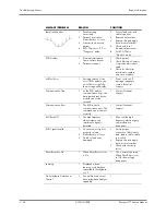
NIBP: Self Test Error

1

Failed self-test.

2

Sensor or A/D sampling 

may have error.

1

Power cycle unit. If 

message reappears, 

contact Technical 

Support.

NIBP: Communication Error

1

NIBP module 

communication error. The 

command can not be sent 

correctly.

1

Power cycle unit. If 

message reappears, 

contact Technical 

Support.

NIBP: System Error

1

System error. After start-

up, the inflating pump, 

A/D sampling unit or 

pressure sensor may have 

error or the pointer may 

have error when the 

software is running. 

2

Power supply is not stable 

or circuit failure leads to 

voltage error.

1

Power cycle unit. If 

message reappears, 

contact Technical 

Support.

NIBP: Cuff Overpressure

1

The hardware 

overpressure limit has 

been exceeded.

2

Overpressure. The cuff 

pressure exceeds 297 

mmHg in ADU mode, 

240 mmHg in PED mode 

or 147 mmHg in NEO 

mode. 

1

Power cycle unit.If 

message reappears, 

contact Technical 

Support.

NIBP: Pneumatic Leak

1

Leakage. In Pneumatic 

check, air leakage is 

found in hose.

1

Change the cuff.

NIBP: Unable to Measure

1

Unable to make 

measurement after three 

automatic retries.

1

Check Patient.

2

Retry measurement. If 

message reappears, 

power cycle unit. If 

message reappears, 

contact Technical 

Support.

NIBP: Reset Failed

1

Reset failed.

1

Power cycle unit.If 

message reappears, 

contact Technical 

Support.

Summary of Contents for Passport V

Page 1: ...Service Manual ...

Page 2: ...cal Ltd Microstream is a U S registered trademark of Oridion Medical Ltd Navigator is a U S trademark of Mindray DS USA Inc Nellcor is a U S trademark of Nellcor Puritan Bennett Inc NIV Line is a trademark of Oridion Medical Ltd Oxiband is a U S registered trademark of Nellcor Puritan Bennett Inc OxiMax is a U S trademark of Nellcor Puritan Bennett Inc Oxisensor is a U S registered trademark of Ne...

Page 3: ...y 3 4 Removal of the Main Board 3 5 Removal of the Inverter 3 6 Removal of the LCD Panel 3 7 Removal of the Keyboard 3 8 Removal of the Alarm LED Board 3 9 Removal of the Encoder 3 9 Removal of the Multi parameter Board Assembly 3 10 Removal of the Parameter Front Panel Assembly 3 12 Removal of the Multi parameter board 3 13 Removal of the CO2 Module 3 13 Removal of the Masimo SpO2 Module 3 14 Rem...

Page 4: ...P N 040 000055 00 3 34 P N 040 000056 00 3 34 P N 040 000057 00 3 35 P N 040 000058 00 3 35 P N 040 000091 00 3 35 P N 040 0000100 00 3 36 P N 040 000224 00 3 36 Troubleshooting Menus 3 37 ECG Troubleshooting 3 37 NIBP Troubleshooting 3 39 SpO2 Troubleshooting 3 40 Temperature Troubleshooting 3 42 Resp Troubleshooting 3 43 IBP Troubleshooting 3 44 CO2 Troubleshooting 3 45 Gas Module Troubleshootin...

Page 5: ...ification 5 12 Initial Set up 5 12 ECG 5 13 Initialization 5 13 Leads OFF 5 13 Pacer Detect 5 13 Performance Test 5 14 IBP 1 and IBP 2 Verification 5 14 Temperature Verification 5 14 SpO2 Verification 5 14 NIBP Verification 5 14 Battery Operation Verification 5 15 CO2 Operation Verification 5 15 Leakage Current Tests 5 15 Preventative Maintenance 6 1 User Preventative Maintenance Introduction 6 1 ...

Page 6: ...less Cuffs 6 8 Disposable Blood Pressure Cuffs 6 8 Care and Cleaning of Gas Module 6 9 Care and Cleaning of 3 and 5 lead ECG Cables and Leadwires 6 10 Battery Replacement and Maintenance 6 11 Battery Replacement 6 11 Battery Maintenance 6 11 Recorder Maintenance 6 12 Cleaning the Recorder Printhead 6 12 Recorder Paper Replacement 6 12 Care and Storage of Thermal Chart Paper 6 12 Warranty Statement...

Page 7: ...cts A NOTE is provided when additional general information is applicable Warnings WARNING The Passport V operates on line voltages Therefore an electric shock hazard may exist when the instrument covers are removed Repair and calibration procedures should only be performed by qualified personnel who proceed with care and follow proper servicing techniques Warnings are given in various chapters as ...

Page 8: ... the Gas Module while it is on and or plugged in CAUTION The internal sampling system of the Gas Module does not need to be cleaned or sterilized There is no reverse flow back to the patient If the internal sampling system is suspected to be clogged or dirty the module should be serviced by an authorized service person only CAUTION To avoid permanent damage do not expose metal components e g pins ...

Page 9: ...g displaying reviewing storing and transferring of multiple physiological parameters including ECG respiration Resp temperature Temp SpO2 pulse rate PR non invasive blood pressure NIBP invasive blood pressure IBP End tidal CO2 value EtCO2 and anesthetic gas AG of single adult pediatric and neonatal patients FIGURE 1 1 The Passport V Monitor ...

Page 10: ... the Patient Monitor The Passport V can be mounted on a wall mount bracket a rolling stand or a bedrail hook which can be ordered optionally Each type of mounting solution is delivered with a complete set of mounting hardware and instructions Refer to the documentation delivered with the mounting hardware for instructions on assembling mounts 1 2 2 Connectors for Peripheral Devices On the back of ...

Page 11: ... for data or a Gas Module 3 depending on how the monitor is configured 7 AC Power Connector A connector for an AC power source 100 to 240 VAC 50 60Hz 8 Equipotential lug A connector for common ground with other equipment 1 3 Main Unit The Passport V consists of the following Input system keypad knob and power switch Output system LCD panel alarm LED board recorder speaker AC battery status LEDs Pr...

Page 12: ...e CPU board Knob The knob can be pressed or rotated either clockwise or counter clockwise It connects to the keypad Power switch The power switch located at the right side of the monitor is a single throw rocker switch Pressing it will power the monitor on or off The power switch s status is detected by the power management and interface board 1 3 2 Output System LCD Panel The monitor uses an LCD ...

Page 13: ...le FIGURE 1 4 Operating principle MODULE DESCRIPTION Power supply interface Introduces a DC from the CPU board Power module Converts the input power into voltages that fit each module and then forwards them to each module CPU Controls the communications between modules Signal interface Controls the communications between the CPU board and the recorder CPU Drive circuit Receives control signals fro...

Page 14: ...nts are implemented via the CPU board which provides interfaces to A built in display The power management and interface board Between this board and the CPU board the signals of USB Network UART SVGA I2C Speaker GPIO are communicated Among them UART signals finally go to the parameter boards The keypad Between the keypad and the CPU board there are two signal wires one is the UART signal wire and...

Page 15: ...ry and AC status 7 Control the fan and detect its running status the complex control algorithm is implemented via the CPU board 8 Detect the internal temperature of the patient monitor On this board there are four sub boards 3 3V and 5V DC board 12V DC board and two battery charge boards The 3 3V and 5V DC board converts the DC source into 5V and 3 3V The 12V DC board converts the DC source into 1...

Page 16: ...E 1 6 The USB hub This board provides connections for both wired network and wireless adapter In the figure below switch 2 always stays off during normal use The operator can switch between wired network and wireless adapter through the software UI Then the CPU applies the operator s selection by controlling switch 1 In configuration mode the CPU turns off switch 1 and then turns on switch 2 so th...

Page 17: ...nal r_flag from the multi parameter board goes to the power management and interface board The CPU can select the source of defibrillator synchronization signals by controlling the output of the DAC The signal r_flag also goes to the CPU for a self test Two UART interfaces serial port 1 and serial port 2 from the CPU board are extended as two RS232 level ports via the power management and interfac...

Page 18: ...n OEM SpO2 module then DPM SpO2 functions are overridden CO2 Module There are two types of CO2 modules DPM CO2 and Microstream CO2 The DPM CO2 module measures the CO2 concentration using the NDIR technology It performs a zero calibration periodically to ensure accurate measurements for a long period of time An appropriate compensation can be applied according to the patient environment thus preven...

Page 19: ...surement These measurements correspond to comparisons with auscultatory values measured using the fifth Korotkoff sound within ANSI AAMI SP10 standards for accuracy CUFF PRESSURE SENSOR PRESSURE SENSOR FOR PROTECT PRESSURE SIGNAL AMPLIFIER CIRCUITS PRESSURE SIGNAL AMPLIFIER CIRCUITS FOR PROTECT CPU ASYCHRONOUS SERIAL COMMUNICATION WATCHDOG OVER PRESSURE PROTECT CIRCUIT A D CONVERTER PRESSURE SIGNA...

Page 20: ...Main Unit Theory of Operation 1 12 0070 10 0705 Passport V Service Manual This page intentionally left blank ...

Page 21: ...pO2 Module 6100 30 86335 Nellcor SpO2 Module 6100 30 86336 Microstream CO2 Module 6100 30 86333 DPM CO2 Module 6100 30 86334 Power board AC DC 9211 30 87311 Alarm LED Board 9211 30 87306 Battery interface board assembly 9211 30 87331 Keypad Overlay 6100 20 86264 XX or 6100 20 86341 XX Keypad 6100 20 86265 XX Main board 9211 20 87303 Power management and interface board 6100 20 86294 Back light boa...

Page 22: ...Block Diagram Block Diagrams 2 2 0070 10 0705 Passport V Service Manual 2 2 Block Diagram FIGURE 2 1 Passport V Block Diagram ...

Page 23: ...hort component leads together 2 The instrument covers must not be removed by anyone other than qualified technical personnel who have received supplementary instructions regarding maintenance of medical equipment or have equivalent experience in this area WARNING Internal Electrical Shock Hazard This unit does not contain any user serviceable parts Do not remove instrument covers Refer Servicing t...

Page 24: ...ative to use the designated equipment in order to ensure proper results of any and all test procedures 4 Clean up the repair area After any repair especially after any soldering or desoldering clean off the repair area with alcohol and a stiff brush This will remove any residual solder flux in turn allowing the instrument to return to its original appearance 3 4 Special Tools Required Digital Volt...

Page 25: ...Carefully remove the knob with a pair of pliers that have protection on the jaws Some pliers may damage the knob FIGURE 3 1 Remove the knob 3 Release the key panel s four clips from the bottom of the unit with a flat bladed screwdriver FIGURE 3 2 Release the key panel clips 4 Remove the key panel from the front 5 Remove the keys and place to the side with the key panel ...

Page 26: ...ce 2 Remove the six screws from the rear of the unit FIGURE 3 3 Remove the screws from the rear of the unit 3 Turn the unit over and carefully separate the front housing assembly and rear housing assembly 4 Disconnect the 50 pin ribbon cable from the front housing assembly FIGURE 3 4 Disconnect the ribbon cable from the front housing assembly 5 Remove the front housing assembly ...

Page 27: ...ing assembly as stated in Removal of the Front Housing Assembly on page 3 4 2 Remove the keyboard cable 3 Remove the inverter cable 4 Remove the LCD panel cable 5 Remove the alarm LED board cable 6 Remove the five screws that secure the main board to the front housing bracket 7 Remove the main board carefully FIGURE 3 5 Remove the main board ...

Page 28: ...emove the front housing assembly as stated in Removal of the Front Housing Assembly on page 3 4 2 Remove the inverter cable 3 Remove the two backlight board cable from the inverter 4 Remove the two screws that secure the inverter to the front housing bracket 5 Remove the inverter carefully FIGURE 3 6 Remove the inverter ...

Page 29: ...ated in Removal of the Front Housing Assembly on page 3 4 2 Remove the two backlight board cables from the inverter 3 Remove the keyboard cable 4 Remove the alarm LED board cable 5 Remove the LCD panel cable 6 Remove the eight screws that secure the front housing bracket 7 Remove the front housing bracket and place to the side FIGURE 3 7 Remove the LCD panel ...

Page 30: ...3 5 6 Removal of the Keyboard 1 Remove the front housing assembly as stated in Removal of the Front Housing Assembly on page 3 4 2 Remove the keyboard cable 3 Remove the encoder cable 4 Remove the four screws that secure the keyboard to the front housing 5 Remove the four keyboard pads 6 Release the clip on the right side of the keyboard and remove the keyboard carefully FIGURE 3 9 Remove the Keyb...

Page 31: ... 4 2 Remove the alarm LED board cable 3 Remove the two screws that secure the board to the front housing 4 Remove the alarm LED board and light conducting pipe carefully FIGURE 3 10 Remove the alarm LED board 3 5 8 Removal of the Encoder 1 Remove the front housing assembly as stated in Removal of the Front Housing Assembly on page 3 4 2 Remove the encoder cable from the keyboard FIGURE 3 11 Discon...

Page 32: ...e the encoder carefully FIGURE 3 12 Remove the encoder 3 5 9 Removal of the Multi parameter Board Assembly 1 Remove the front housing assembly as stated in Removal of the Front Housing Assembly on page 3 4 2 Disconnect the 50 pin ribbon cable from the interface board 3 Disconnect the cable from J15 of the interface board 4 Disconnect the NIBP communication cable from the interface board FIGURE 3 1...

Page 33: ...move the four screws that secure the assembly to the rear housing and main frame 6 Disconnect the CO2 tubing and cable from the multi parameter board assembly if CO2 module is configured 7 Remove the multi parameter board assembly carefully FIGURE 3 14 Remove the multi parameter board assembly ...

Page 34: ...bly on page 3 10 2 Unplug the tubing from the NIBP connector FIGURE 3 15 Unplug the tubing from the NIBP connector 3 Unfasten the two screws that secure the SpO2 connector and then remove the connector if Masimo or Nellcor SpO2 module is configured 4 Remove the three screws that secure the parameter front panel 5 Remove the parameter front panel FIGURE 3 18 Remove the parameter front panel FIGURE ...

Page 35: ...rd 3 Remove the multi parameter board FIGURE 3 19 Remove the multi parameter board 3 5 12 Removal of the CO2 Module 1 Remove the multi parameter board assembly as stated in Removal of the Multi parameter Board Assembly on page 3 10 2 Remove the two screws that secure the module to the main frame 3 Remove the CO2 module 4 Remove the water trap connector assembly or microstream CO2 connector fixture...

Page 36: ...rame 5 Unfasten the two screws that secure the Masimo SpO2 connector 6 Remove the Masimo SpO2 module FIGURE 3 22 Remove the Masimo SpO2 module 3 5 14 Removal of the Nellcor SpO2 Module 1 Remove the multi parameter board assembly as stated in Removal of the Multi parameter Board Assembly on page 3 10 2 Disconnect the SpO2 communication cable from the multi parameter board 3 Cut the tie of flexible ...

Page 37: ...BP gas nipple 3 Disconnect the NIBP communication cable from the NIBP board 4 Unfasten the screws that secure the NIBP assembly to the multi parameter board installation frame 5 Remove the NIBP assembly FIGURE 3 24 Remove the NIBP assembly 3 5 16 Removal of the Recorder Assembly 1 Remove the two screws that secure the recorder 2 Release the two clips and pull out the recorder FIGURE 3 25 Remove th...

Page 38: ...and Multi parameter Board Assembly 1 Remove the front housing assembly as stated in Removal of the Front Housing Assembly on page 3 4 2 Remove the recorder assembly if installed as stated in Removal of the Recorder Assembly on page 3 15 3 Disconnect the power switch cable from the interface board 4 Remove the eight screws that secure the main frame and multi parameter board assembly to the rear ho...

Page 39: ...embly 3 5 19 Removal of the Speaker Assembly 1 Remove the main frame and multi parameter board assembly as stated in Removal of the Main Frame and Multi parameter Board Assembly on page 3 16 2 Cut the clamp that secures the speaker cable 3 Disconnect the speaker cable from the interface board FIGURE 3 29 Disconnect the speaker cable from the interface board 4 Remove the three screws that secure th...

Page 40: ...sembly as stated in Removal of the Main Frame and Multi parameter Board Assembly on page 3 16 2 Cut the clamp that secures the fan cable 3 Disconnect the fan cable from the interface board FIGURE 3 31 Disconnect the fan cable from the interface board 4 Remove the fan EVA cushion 5 Remove the two screws that secure the fan FIGURE 3 32 Remove the fan assembly 6 Remove the fan ...

Page 41: ... two screws that secure the CF card assembly 3 Disconnect the CF card cable 4 Remove the CF card assembly FIGURE 3 33 Remove the CF card assembly 3 5 22 Removal of the Power Board 1 Remove the main frame and multi parameter board assembly as stated in Removal of the Main Frame and Multi parameter Board Assembly on page 3 16 2 Remove the two screws that secure the recorder connecting board and then...

Page 42: ...r board connecting cable from the interface board FIGURE 3 35 Disconnect the power board connecting cable 4 Remove the three screws that secure the power socket support from the back of the main frame 5 Remove the screw that secures the grounding wire FIGURE 3 36 Remove the screws that secure the power socket ...

Page 43: ...e the power board 3 5 23 Removal of the Li ion Battery Interface Board Assembly 1 Remove the front housing assembly as stated in Removal of the Front Housing Assembly on page 3 4 2 Remove the recorder assembly if installed as stated in Removal of the Recorder Assembly on page 3 15 3 Remove the two screws that secure the recorder connecting board and then remove the board FIGURE 3 38 Remove the scr...

Page 44: ...battery interface board cable from the interface board FIGURE 3 39 Disconnect the Li ion battery interface board cable 5 Remove the four nuts that secure the Li ion battery interface board assembly 6 Remove the Li ion battery interface board assembly FIGURE 3 40 remove the Li ion battery interface board assembly ...

Page 45: ... 15 3 Disconnect the power switch cable from the interface board 4 Remove the six screws that secure the main frame to the rear housing FIGURE 3 41 Remove the screws from the main frame 5 Remove the two screws that secure the main frame from the bottom 6 Remove the main frame assembly and place to the side FIGURE 3 42 Remove the screws securing the main frame 7 Disconnect the Li ion battery interf...

Page 46: ...isconnect the fan cable from the interface board 12 Disconnect the CF card cable from the interface board 13 Disconnect the wireless AP if installed cable from the interface board FIGURE 3 44 Disconnect the cables from the interface board 14 Remove the two screws that secure the interface board assembly to the main frame 15 Remove the interface board assembly FIGURE 3 45 Remove the interface board...

Page 47: ... 2 Remove the recorder assembly if installed as stated in Removal of the Recorder Assembly on page 3 15 3 Disconnect the power switch cable from the interface board 4 Remove the six screws that secure the main frame to the rear housing FIGURE 3 46 Remove the screws from the main frame 5 Remove the two screws that secure the main frame from the bottom 6 Remove the main frame assembly FIGURE 3 47 Re...

Page 48: ...ce Manual 7 Remove the nut that secures the wireless AP to the main frame FIGURE 3 48 Remove the nut securing the wireless AP to the main frame 8 Disconnect the wireless AP cable from the wireless AP 9 Remove the wireless AP FIGURE 3 49 Disconnect the cables from the wireless AP ...

Page 49: ...ce Manual 0070 10 0705 3 27 Repair Information Nurse Call Cable 3 6 Nurse Call Cable 3 6 1 P N 8000 21 10361 FIGURE 3 50 Nurse Call Cable 3 7 Analog Output Cable 3 7 1 P N 6100 20 86360 FIGURE 3 51 Analog Output Cable ...

Page 50: ...Defib Synch Cable Repair Information 3 28 0070 10 0705 Passport V Service Manual 3 8 Defib Synch Cable 3 8 1 P N 6100 20 86361 FIGURE 3 52 Defib Synch Cable ...

Page 51: ...tion Serial Port to Gas Module 3 Cable 3 9 Serial Port to Gas Module 3 Cable 3 9 1 P N 0012 00 1276 XX FIGURE 3 53 Serial Port to Gas Module 3 Cable DESCRIPTION DASH NUMBER 12 9 pin mini D serial to 25 pin D shell 01 72 9 pin mini D serial to 25 pin D shell 02 ...

Page 52: ...Null Modem Cable Repair Information 3 30 0070 10 0705 Passport V Service Manual 3 10 Null Modem Cable 3 10 1 P N 0012 00 1275 01 FIGURE 3 54 Null Modem Cable ...

Page 53: ...l ECG Lead Wires 3 11 Universal ECG Lead Wires 3 11 1 P N 0012 00 1503 XX FIGURE 3 55 Universal ECG Lead Wires DESCRIPTION DASH 10 24 snap 5 lead set Domestic 02 11 24 snap 3 lead set Domestic 05 12 24 snap 5 lead set International 11 13 24 snap 3 lead set International 14 ...

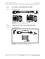
Page 54: ...05 Passport V Service Manual 3 12 ECG Cable 3 5 lead ESIS and Non ESIS 3 12 1 P N 0012 00 1745 XX FIGURE 3 56 ECG Cable 3 5 lead ESIS and Non ESIS 3 13 12 pin 3 lead Neo ECG Trunk Cable IEC AHA 3 13 1 P N 040 000072 00 FIGURE 3 57 12 pin 3 lead Neo ECG Trunk Cable IEC AHA ...

Page 55: ...3 Repair Information IBP Cable 3 14 IBP Cable 3 14 1 P N 040 000052 00 FIGURE 3 58 5 pin IBP Cable IM2301 Hospira 3 14 2 P N 040 000053 00 FIGURE 3 59 5 pin IBP Cable IM2302 BD 3 14 3 P N 040 000054 00 FIGURE 3 60 5 pin IBP Cable IM2303 Edwards ...

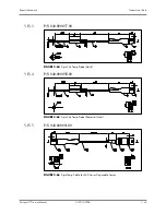
Page 56: ... Manual 3 14 4 P N 040 000096 00 FIGURE 3 61 IBP Adapter Cable 5 pin to 6 pin 3 15 Temperature Cable 3 15 1 1 15 1 P N 040 000055 00 FIGURE 3 62 5 pin Esophageal Rectal Temp Probe Adult 3 15 2 P N 040 000056 00 FIGURE 3 63 5 pin Esophageal Rectal Temp Probe Pediatric Infant ...

Page 57: ...formation Temperature Cable 3 15 3 P N 040 000057 00 FIGURE 3 64 5 pin Skin Temp Probe Adult 3 15 4 P N 040 000058 00 FIGURE 3 65 5 pin Skin Temp Probe Pediatric Infant 3 15 5 P N 040 000091 00 FIGURE 3 66 5 pin Temp Cable for 400 Series Disposable Sensor ...

Page 58: ...formation 3 36 0070 10 0705 Passport V Service Manual 3 15 6 P N 040 0000100 00 FIGURE 3 67 5 pin Temp Adapter Cable 5 pin to 6 35 Phone 3 15 7 P N 040 000224 00 FIGURE 3 68 5 pin Temp Cable for MRS Disposable Sensor 5 5 DC Jack ...

Page 59: ...de placement 1 Repeat skin preparation and electrode location procedures 2 Apply fresh moist electrodes 3 Avoid areas of the torso that are very muscular Excessive alarms heart rate lead fault 1 Electrodes dry 2 Alarm limits set too close to patient s normal heart rate 3 R wave wrong size 4 Excessive patient movement or muscle tremor 1 Re prep skin and apply fresh moist electrodes 2 Readjust 3 Mus...

Page 60: ...nication Stop 1 As the ECG module communication stops the data packets sent by the module can not be received 1 Contact Technical Support Communication Error 1 The ECG module communication error The command can not be sent correctly 1 Contact Technical Support ESU Resp Off 1 The high frequency electrosurgery unit interference signal is detected 1 Wait until the high frequency electrosurgery unit i...

Page 61: ...tact Technical Support NIBP System Error 1 System error After start up the inflating pump A D sampling unit or pressure sensor may have error or the pointer may have error when the software is running 2 Power supply is not stable or circuit failure leads to voltage error 1 Power cycle unit If message reappears contact Technical Support NIBP Cuff Overpressure 1 The hardware overpressure limit has b...

Page 62: ... movement Switch cuff to another limb NIBP Initialization Error 1 During the IBP module power on as the IBP module communication stops system fails to communicate with module 1 Contact Technical Support NIBP Communication Stop 1 As the Resp module communication stops the data packets sent by the module can not be received 1 Contact Technical Support MESSAGE PROBLEM REASON SOLUTION MESSAGE PROBLEM ...

Page 63: ...O2 Motion Nellcor Only 1 Motion is detected 1 Decrease patient motion check sensor SpO2 Weak Pulse Nellcor Only 1 Low pulse amplitude 1 Contact Technical Support SpO2 Low Signal Nellcor Only 1 The SpO2 signal is too low or too weak 1 Check sensor placement move as necessary 2 Switch limb Notify physician SpO2 Check Sensor Nellcor Only 1 The SpO2 module has sensed a poor connection or a bad sensor ...

Page 64: ...e not displayed 1 Improper display setup 2 Cable not plugged in 1 Check display setup in Monitor Setup Menu and change as desired 2 Check the cable Temp Communication Stop 1 As the Temp module communication stops the data packets sent by the Temp module can not be received 1 Contact Technical Support Temp Communication Error 1 Temp module communication error The command can not be send correctly 1...

Page 65: ...Check that proper patient cable is used Use non ESIS patient cable 3 Check cable CHK Lead Message 1 Increased impedance caused by one of the following 2 Chest hair under electrodes 3 Dried electrode gel 4 Electrode off Lead off 5 Cracked lead wires 6 Poor skin prep 1 Prep chest 2 Change electrodes 3 Replace electrode 4 Replace lead 5 Replace lead wires 6 Clean and abrade skin before applying elect...

Page 66: ...hysician IBP not Displayed No IBP Waveform 1 Improper Setup 2 Cable not plugged in 3 Transducer not connected 4 Stopcock turned improperly 5 Transducer not zeroed 1 Check display setup in monitor setup 2 Check cable 3 Check transducer connection 4 Check transducer 5 Check and zero the transducer Abnormally High or Low readings 1 Transducer too HIGH or too LOW 1 Check patient adjust transducer re z...

Page 67: ...w sample line CO2 Occlusion Microstream only 1 Sample line is blocked or kinked 1 Check sample line Clear blockage or kink or replace with a new sample line CO2 Sensor High Temperature DPM only 1 Temperature over ranges high limit checked by module 1 Check stop using or replace the sensor CO2 Sensor Low Temperature DPM only 1 Temperature over ranges low limit checked by module 1 Check stop using o...

Page 68: ... Sending out order is failed during work 1 Contact Technical Support CO2 Check Airway Microstream only 1 Airway Error 1 Check airway connection CO2 Main Board Error Microstream only 1 Module has problems 1 Reset the module 2 Contact Technical Support CO2 Replace Scrubber Pump Microstream only 1 Module has problems 1 Restart the monitor 2 Contact Technical Support CO2 15V Overrange Microstream only...

Page 69: ... 1 Check the CO2 connections After the sensor s temperature becomes stabilized perform a zero calibration again If problem persists contact Technical Support Calibration Error DPM Microstream only 1 The actual concentration of calibration gas applied is in wide discrepancy with the concentration value entered by the user in the Calibration dialog 1 Make sure the concentration value entered is the ...

Page 70: ... gas mixture is attached tightly and regulator is on Repeat calibration procedure If problem persists contact Technical Support GM O2 Uncalibrated 1 Appears after an unsuccessful calibration attempt of the O2 sensor The numeric data for O2 will appear as XXX and the O2 waveform will be a flatline 1 Ensure proper gas mixture is attached tightly and regulator is on Repeat calibration procedure If pr...

Page 71: ...onitor GM Replace Trap 1 Indicates residue build up on the water trap membrane that is decreasing airflow 1 Replace water trap reservoir GM Exhaust Blocked 1 Appears when the system detects a blockage at the exhaust gas outlet as indicated by an increase in internal pressure 1 Remove waste gas scavenging assembly check if message disappears Check exhaust line for blockage and clear if possible If ...

Page 72: ...ion Error 1 System cannot communicate correctly with Resp module and receive the error data packets 1 Restart the monitor If the error still appears please contact Technical Support GM Disconnected 1 Appears when the Passport V cannot detect signals being sent by the Gas Module 1 Ensure Gas Module is turned on and interface cable is properly connected If problem persists contact Technical Support ...

Page 73: ...paper 1 Press Print Trend when trend window is open Use scroll feature to scroll to the top of the trend then press Print Trend 2 Check Replace paper Local Printer Comm Error 1 Thermal paper may be installed incorrectly up side down 1 Remove paper and re install with paper feeding off of the spool from the bottom Local Printer SelfTest Error 1 The printer door is not closed 1 Close the printer doo...

Page 74: ...lence symbol and message 2 Increase beep volume Cooling Fan Failure 1 The unit running on AC power and the cooling fan is not operational 1 Contact Technical Support Patient Information did not appear on display 1 No data entered 2 Done was not selected from keypad after entering data 1 Enter proper patient data 2 Go to the proper keypad enter data and select Done when finished Incorrect Date or T...

Page 75: ...le Silence All Permanent Selection Auxiliary Output Nurse Call Mode Set up Serial Port 1 Set up Serial Port 2 Copy Monitor Defaults to Storage Device Copy Monitor defaults from Storage Device Reboot in demo mode Restore factory defaults Advanced Installation Setup Change Password and Options 1 Enter Installation Mode by pressing and holding the Discharge key while powering on the monitor 2 Set eac...

Page 76: ...Pa mmHg Select to change CO2 units ECG Standard AHA IEC AHA Select to change ECG lead standard Notch Filter 50Hz 60Hz 60Hz Select to change notch filter frequency ESU Filter Auto Disable Auto Select to change ESU Filter setting SpO2 Sensor Off Audio Off Once Repeat Off Select to change SpO2 Sensor Off Audio SpO2 Tones Standard Tones Alternative Tones Standard Tones Select to change the SpO2 tones ...

Page 77: ...ing on the monitor 6 Select Copy Monitor Defaults from Storage Device A status message will report completion of the transfer 7 Select Save Current and power cycle the receiving monitor to enter normal monitoring mode Set up Serial Port 2 None DIAP Gas Module None Select to set up a serial output protocol port Copy Monitor Defaults to Storage Device Select to copy the monitor defaults and settings...

Page 78: ...revious Menu and select using the Navigator Knob MENU TITLE ON SCREEN MENU CHOICES DEFAULT TEXT STRINGS DIAP Baud Rate 9600 19200 9600 Select to change the DIAP baud rate Enable Network Wired Wireless Wired Select to change network IP Address 0 255 192 168 0 100 Select to set up IP Address Subnet Mask ID 0 255 255 255 255 0 Select to set up Subnet Mask ID Configure Wireless AP Select to configure ...

Page 79: ...tion is passed When Update is selected updating will begin When update is complete Permanent will be displayed in Expiration column If Update is selected again before the update is completed updating will be cancelled and will be displayed 3 18 Trend Storage The Passport V monitor is capable of storing in non volatile memory up to 6000 trend data entries When the maximum number of entries has been...

Page 80: ...om the same network is detected the monitor starts to update software The monitor screen will indicate the BIOS version Host software version module version and corresponding status message The status message Upgrade is successful Disconnect the network cable and reboot the monitor will display after download is complete To update by DPM SB storage device select Options in installation mode The up...

Page 81: ...ssport V Service Manual 0070 10 0705 4 1 4 0 Isometric Drawings and Parts List 4 1 Introduction This chapter provides information necessary to identify the replacement parts and assemblies of instruments ...

Page 82: ...Top Level Assembly Isometric Drawings and Parts List 4 2 0070 10 0705 Passport V Service Manual 4 2 Top Level Assembly FIGURE 4 1 Top Level Assembly ...

Page 83: ...thout IBP French 6100 20 86341 53 2 Overlay Keypad Without IBP Spanish 6100 20 86341 54 2 Overlay Keypad Without IBP Italian 6100 20 86341 55 2 Overlay Keypad Without IBP Dutch 6100 20 86341 56 2 Overlay Keypad Without IBP Brazilian Portuguese 6100 20 86341 57 3 Keypad English 6100 20 86265 51 3 Keypad German 6100 20 86265 52 3 Keypad French 6100 20 86265 53 3 Keypad Spanish 6100 20 86265 54 3 Key...

Page 84: ...mbly Parameter board to Interface Board 9211 20 87237 4 Recorder door 043 000184 00 4 Recorder 801 6101 00011 00 5 Power Switch with Cable Assembly 6100 21 86306 6 Screw Pan Head Phillips M3X6 M04 002505 7 Sub assembly Rear Housing N A 8 AC Inlet Hook 9211 20 87369 9 Screw Flat Head Phillips M3X8 M04 000405 10 Sub assembly Main Chassis N A 11 Microstream CO2 Module Assembly 801 6100 00029 00 11 DP...

Page 85: ...6263 6 Encoder Optical 16 pos 5VDC Dip6 0000 10 10789 7 Spring EMI 0000 10 10996 8 Mounting Washer Keypad PCB 6100 20 86269 9 PCBA Keypad 801 6100 00006 00 10 Front housing service kit 801 6100 00005 00 11 Lens Alarm Light 6100 20 86267 12 PCBA Alarm Light 801 6100 00008 00 13 Screw Self Tapping PT2X6 M04 051003 14 LCD TFT 12 1 800x600 3 3V 801 0000 00005 00 15 Screw Flat Head Phillips M3X6 M04 00...

Page 86: ...ts List 4 6 0070 10 0705 Passport V Service Manual 4 5 Rear Housing Sub assembly FIGURE 4 4 Rear Housing Sub assembly ITEM NO DESCRIPTION PART NUMBER 1 Handle service kit 801 6100 00009 00 2 Rear Housing service kit 801 6100 00010 00 3 Foot DA6H 20 22831 ...

Page 87: ...Passport V Service Manual 0070 10 0705 4 7 Isometric Drawings and Parts List Main Chassis Sub assembly 4 6 Main Chassis Sub assembly FIGURE 4 5 Main Chassis Sub assembly ...

Page 88: ...Gasket Speaker pressure plate and spacer 8002 20 36218 15 AC Inlet with Cable Assembly 9211 20 87221 16 Grounding terminal 0509 20 00098 17 Serrated lock washers external teeth GB T862 2 1987 6 plated with anti rustiness nickel M04 021048 18 Washer Grounding pillar 6100 20 86393 19 Bracket AC Inlet N A 20 PCBA Power Supply 801 6100 00015 00 21 Insulator Power Supply Board N A 22 Screw Flat Head Ph...

Page 89: ...g EMI M6T 030006 2 Bracket Interface Board Mounting 6100 20 86277 3 Seal O ring 9 5X1 8 silicone A75 brown M6M 010009 4 Silica gel waterproof wrap SB 6100 20 86275 5 PCBA Power Supply Management and Interface Use assembly P N 801 6100 00025 00 6 Bracket Interface Board Top N A 7 Bracket Interface Board Bottom N A 8 Gasket Network Socket 9211 20 87440 9 Screw Pan Head W Washer Phillips M3X6 M04 004...

Page 90: ...n Head W Washer Phillips M3X6 M04 004012 2 Module Integrated Parameter 801 6100 00017 00 3 Frame Parameter Board Mounting 6100 20 86276 4 Cable Assembly NIBP 6100 20 86305 5 NIBP Module Assembly 801 6100 00026 00 6 Masimo SpO2 Module Assembly 801 6100 00028 00 6 Nellcor SpO2 Module Assembly 801 6100 00027 00 6 DPM SpO2 Module Assembly 801 6100 00024 00 7 Sub assembly Patient Connector 801 6100 000...

Page 91: ...onnector Sub assembly ITEM NO DESCRIPTION PART NUMBER 1 Blank Cover Plate CO2 Opening 6100 20 86297 1 Watertrap assembly Sidestream CO2 See DPM CO2 Module Assembly 1 Assembly Micro stream CO2 Receptacle 801 6100 00020 00 2 Gas Outlet 6200 20 11614 3 Assembly NIBP Connector DA6H 20 22833 4 Parameter Connector Panel 6100 30 86328 5 Nut Stainless Steel M5 GB6170 N A ...

Page 92: ...ng Silicone 1 16 X 3 16 TYGON 3350 1feet M6G 020006 6 Air filter hose ID 1 8 25um S1 0378 02 0004 7 Valve Quick Deflate 801 6101 00012 00 8 Screw Pan Head Phillips M3X18 N A 9 Proportional solenoid valve normally open 801 6101 00013 00 10 Frame NIBP Tubing Retaining N A 11 Tubing Silicone Five Branch N A 12 Screw Pan Head Phillips M3X6 N A 13 TUBE Silicone 1 8 X 1 4 X100ft 2800546 100 A21 000002 1...

Page 93: ...y ITEM NO DESCRIPTION PART NUMBER 1 Screw Pan Head W Washer Phillips M3X6 N A 2 Bracket Micro Stream CO2 Mounting N A 3 Cable Assembly Micro Stream CO2 to Transfer Board 9201 20 35932 4 PCBA Micro Stream CO2 Transfer N A 5 Cable Assembly Micro Stream CO2 9211 20 87247 6 Screw Pan Head Phillips M3X6 N A 7 Module Micro Stream CO2 N A 8 Assembly Micro stream CO2 Receptacle 801 6100 00020 00 ...

Page 94: ...Screw Pan Head Cross Recessed M3X6 N A 4 Moisture exchanger Nafion Tube for DPM CO2 M02A 10 25936 5 Cushion water trap receptacle 6100 20 86355 6 Mounting Frame DRYLINE Flush 040 000226 00 7 Screw Pan head Self Tapping PT2X6 N A 8 Tubing ID 1 16 OD 1 8 20feet 3001 10 07069 9 Flush Mount Water Trap 040 000225 00 10 Flow restrictor tube M02A 21 25944 11 Cable Assembly Watertrap cable 009 000101 00 1...

Page 95: ...ew Stud M3X7 N A 4 PCBA Masimo Transfer Board 801 6101 00015 00 5 Communication cable OEM SpO2 9211 20 87242 6 Screw Pan Head W Washer Phillips M3X6 M04 004012 7 Nut Stainless Steel M3 GB6170 N A 8 Washer insulating 3X1mm N A 9 SpO2 flex cable assembly 2685 040 000150 00 10 Screw Flat Head PhillipsM2 5X4 N A 11 Frame Masimo SpO2 Connector 6101 20 46720 52 12 Screw Self Tapping PT3X8 N A 13 Screw P...

Page 96: ...ervice kit 801 6100 00023 00 2 Nellcor cable assembly 801 6100 00022 00 3 Screw Flat Head Phillips M2 5X4 N A 4 Frame Nellcor SpO2 Interface 6101 20 46719 52 5 Screw Self Tapping PT3X8 N A 6 Nut Stud M3X12 N A 7 Screw Phillips Pan Head Washer M3X18 N A 8 Isolated power and signal conversion board PCBA Nellcor SpO2 module 801 6101 00017 00 9 Communication cable OEM SpO2 9211 20 87242 10 Screw Pan H...

Page 97: ...rt V user interface is used to execute all tests CAUTION Calibration is not to be performed while monitoring a patient 5 2 Warnings and Guidelines If the instrument covers are removed observe the following warnings and general guidelines 1 Do not short component leads together 2 Perform all steps in the exact order given 3 Use extreme care when reaching inside the opened instrument Do not contact ...

Page 98: ...r CO2 Calibration Gas P N 0075 00 0033 01 Calibration Gas Regulator P N 0119 00 0166 GM Calibration Gas P N 0075 00 0028 Safety Analyzer 601 safety analyzer Demsey Model 431 or equivalent 5 4 Services To enter the Service mode 1 Turn the power OFF 2 Press and hold the Mark Event key while powering on the monitor The Service Menu will appear on screen Release the Mark Event key 3 Rotate the Navigat...

Page 99: ...mplitude becomes greater or smaller If so the ECG module must be serviced FIGURE 5 2 ECG Channels Check Menu 1 Select the ECG Channels Check button in the Service Menu 2 Use the NavigatorTM Knob to select the Start Channels Check button and activate the test A square wave should appear on the screen 3 Compare the amplitude of the square wave with the wave scale The difference should be within 5 ...

Page 100: ... shown in FIGURE 5 4 2 Select NIBP Accuracy Test using the NavigatorTM Knob to activate the test 3 Using the manometer s bulb valve raise the pressure in the test chamber to 300mmHg 4 Compare the pressure displayed on the screen with the pressure viewed on the manometer The difference between readings should not be greater than 3 mmHg NOTE An NIBP simulator can be used to replace the reference man...

Page 101: ... appears 5 4 2 3 NIBP Calibration The purpose of this test is to verify the pressure transducer sensitivity for optimal accuracy 1 Connect the equipment as shown in FIGURE 5 4 2 Use the NavigatorTM Knob to select Calibrate NIBP 3 Select Inflate to activate the calibration At the same time the Inflate button changes to Accept 4 Select Reference Pressure to set the calibration reference pressure NOT...

Page 102: ...Select Calibrate Pressure to set the calibration reference pressure The default pressure is 200 mmHg NOTE The Calibrate Pressure is adjustable from 80 mmHg to 300 mmHg at 2 mmHg intervals 5 Adjust the simulator to match the calibration reference pressure 6 If the value in the Calibrate IBP Menu does not match the calibration reference pressure select Calibrate to calibrate the pressure module FIGU...

Page 103: ... 1 intervals For the MicrostreamCO2 module it can be adjusted from 4 0 to 6 0 at 0 1 intervals 5 Make sure the CO2 tubing is vented before flowing the gas CO2 readings will appear during the calibration NOTE If the Sidestream CO2 module is used the Calibrate CO2 Menu will show the measured CO2 concentration atmospheric pressure and sensor temperature If the Microstream CO2 module is used the Calib...

Page 104: ... Gas 2 Connect the gas bottle and the tubing using a T connector as shown in FIGURE 5 8 3 Check the airway and make sure that there is no occlusion or leakage 4 Press the Gas Selection button to select the type of calibration gas 5 Select Start to activate a calibration At the start of the calibration the message Zeroing will be displayed for each of the gas labels as the Gas Module zeros the gas ...

Page 105: ...If at least one gas was successfully measured the Accept menu choice will become available If the values are acceptable select Accept To cancel the calibration and restore the previous calibration data select Abort NOTE When the Accept menu choice is selected the message Disconnect Calibration Gas will be displayed To avoid premature emptying of the gas bottle always remove the regulator at the en...

Page 106: ...Services Calibration Procedure 5 10 0070 10 0705 Passport V Service Manual FIGURE 5 9 Calibration ...

Page 107: ...Log Menu 1 Select the Monitor Log using the NavigatorTM Knob to enter the Monitor Log Menu 2 Errors log will appear on screen Each error is time stamped and dated 3 Use the NavigatorTM Knob to move the cursor within the list of errors 4 To clear all data from the error log use the NavigatorTM Knob to select Clear ...

Page 108: ... Display Setup 3 Waveforms 2 ECG Speed 25 mm sec 3 IBP Speed 25 mm sec optional 4 Respiration Gas Speed 12 5 mm sec B Print Setup 1 Waveform 1 ECG 1 2 Waveform 2 ECG 2 3 Select Printer Local C Parameters 1 ECG a ECG 1 II b ECG 2 I c ECG 3 III d ECG 1 thru 6 Size 1 cm mV e ECG 1 I f ECG 2 II g ECG 3 III h ECG 4 AVR i ECG 5 AVL j ECG 6 AVF k ECG 7 V 2 NIBP a Set Start Pressure 180 mmHg Interval 5 mi...

Page 109: ... LL LA and C V from the simulator and observe that the message Lead OFF appears on the display 2 Set the ECG simulator to Short Leads Verify that the resolution does not exceed one pixel 5 5 2 3 Pacer Detect 1 Set the Pacer Enhancement feature to ON in the ECG Setup Menu 2 Set the ECG simulator to Ventricular Pacer 3 Verify the pacer pulse white line is displayed before the R wave of the QRS signa...

Page 110: ...he systolic diastolic and mean values display as 0 1mm Hg 3 Apply 50 150 and 300 mmHg and verify that Sys Dia Mean parameters match 4 Apply a 120 80 mmHg signal into IBP 1 and apply a 60 20 mmHg signal into IBP 2 and verify that the correct waveforms are displayed on the screen 5 5 4 Temperature Verification 400 Series Probe 1 Set the Simulator to 37 C Connect to the monitor using a 400 series pro...

Page 111: ... the FilterLine Short Term assembly to the input port of the CO2 connector on the left side of the monitor 2 Attach a can of Calibration Gas P N 0075 00 0033 01 to the Filterline Short Term assembly Feed gas into monitor and verify the ETCO2 Inspired CO2 and respiration readings are displayed on the screen 5 5 9 Leakage Current Tests 1 Plug the line cord of the unit into the safety analyzer Connec...

Page 112: ... equipotential lug of the monitor 3 Connect the ECG cable from the Analyzer to the monitor 4 On the safety analyzer depress the Apply 115 VAC button and note the reading 5 Repeat the test for normal and open ground polarity combinations Specifications Verify the current readings of the test are below 50µA under a single fault condition ...

Page 113: ...s The Passport V Monitor is designed for stable operation over long periods of time Under normal circumstances the monitor should not require technical maintenance beyond that described in this chapter However routine maintenance calibration and safety checks are recommended at least once a year or more often as required by local statutory or hospital administration practice ...

Page 114: ...einstalled 6 2 3 Power on test 1 Perform when first installed or reinstalled 2 Perform following any maintenance or the replacement of any main unit parts 6 2 4 Perform NIBP Verification and Calibration Annually 1 Perform NIBP test See NIBP Verification on page 5 14 2 Perform NIBP calibration See NIBP Calibration on page 5 5 6 2 5 Perform CO2 Verification and Calibration Annually 1 Perform CO2 tes...

Page 115: ...fication on page 5 12 2 Perform Gas calibration See Gas Calibration on page 5 8 6 2 9 Temperature Perform Verification Annually 1 Perform temperature test See Temperature Verification on page 5 14 6 2 10 SpO2 Perform Verification Annually 1 Perform SpO2 test See SpO2 Verification on page 5 14 6 2 11 Electrical Safety Tests Annually 1 Perform test See Leakage Current Tests on page 5 15 ...

Page 116: ...ing solution or a fine soft hair brush DO NOT use abrasive cleaning materials Remove fingerprints and stains with a liquid lens cleaner and a soft cloth DO NOT wipe a dry screen or use alcohol or solvents containing chlorinated hydrocarbon 6 3 1 Decontamination of the Monitor WARNING Perform the decontamination process with the unit powered off and the power cord removed Decontamination of a unit ...

Page 117: ...attempt to sterilize 6 4 1 Cleaning and Re use of a Nellcor Sensor Sensors may be reattached to the same patient if the emitter and detector windows are clear and the adhesive still adheres to the skin The adhesive can be partially rejuvenated by wiping with an alcohol wipe and allowing the sensor to thoroughly air dry prior to replacement on the patient Do not immerse any Oxisensor OxiMax Durasen...

Page 118: ...nents Preventative Maintenance 6 6 0070 10 0705 Passport V Service Manual 6 5 Cleaning CO2 Sensors Adapters and Sampling Components Microstream CO2 patient monitoring accessories are designed for single patient use and should not be cleaned or reused ...

Page 119: ...sinfected with a damp cloth with 70 isopropanol and water It may also be disinfected with ultraviolet The bladder can only be disinfected with ultraviolet NOTE Prolonged use of disinfectant may cause discoloration of the cuff Replace the bladder after cleaning and disinfecting the cuff as follows 1 Place the bladder on the top of the cuff as the figure shows 2 Roll the bladder lengthwise and inser...

Page 120: ...mmended because chlorine will chemically break down the urethane on the inside of the cuff Antimicrobial Definition Bladderless cuffs are treated with an antimicrobial coating Antimicrobial technology effectively controls a broad spectrum of bacteria fungi algae and yeasts on a wide variety of treated substrates 6 6 3 Disposable Blood Pressure Cuffs Disposable cuffs are intended for single patient...

Page 121: ...odule should be serviced by an authorized service person only 1 The Water Trap Reservoir must be checked and emptied whenever changing patients or if it is more than half full To remove the water trap push the water trap latch to the right The water trap is spring loaded and will pop out An Air Leak message will be displayed The monitor will suspend sampling Detach the reservoir from the water tra...

Page 122: ...utaraldehyde solution i e Cidex is recommended After cleaning the ECG cables and leadwires should be wiped with water using a clean damp cloth and then dried with a clean dry cloth CAUTION To avoid permanent damage do not expose metal components pins sockets snaps to disinfectants soaps or chemicals NOTE ECG cables and leadwires must never be immersed soaked in any fluids and they should not be cl...

Page 123: ... place 4 Close battery compartment door by sliding the door to the right until it firmly clicks into place 6 9 2 Battery Maintenance The batteries may be subject to local regulations regarding disposal At the end of the battery life dispose of the batteries in accordance with any local regulations CAUTION Recharge batteries in the Passport V CAUTION Remove the batteries if the Passport V is not li...

Page 124: ... is acceptable and reduces print head wear 1 Use the latch at the upper right corner of the recorder door to pull the door open 2 Remove the empty paper spool 3 Insert a new paper roll so that it fits snugly into its housing and the sensitive side of the paper faces the print head at the top of the recorder paper feeding off of the spool from the bottom 4 Pull out approximately 4 inches of paper 5...

Page 125: ...avoided Solvent Reactions Do not store the recordings in plastic bags acetate sheet protectors or similar items made from petroleum products These products emit a small amount of vapor which will over a period of time deteriorate the image on the chart paper Adhesive Tape Never place adhesive tape over recordings The reaction between the adhesive compound and the chemical thermal paper can destroy...

Page 126: ...DS USA Inc will not be liable for any incidental special or consequential loss damage or expense directly or indirectly arising from the use of its products liability under this warranty and the buyer s exclusive remedy under this warranty is limited to servicing or replacing at Mindray s option at the factory or at an authorized Distributor any product which shall under normal use and service app...

Page 127: ...der normal use and service appear to the Company to have been defective in material or workmanship No agent employee or representative of Mindray DS USA Inc has any authority to bind Mindray DS USA Inc to any affirmation representation or warranty concerning its products and any affirmation representation or warranty made by any agent employee or representative shall not be enforceable by buyer Th...

Page 128: ...strument model number the serial number and a description of the problem with all requests for service Any questions regarding the warranty should be directed to the closest authorized location A list of international offices along with their phone numbers is provided at the end of this manual 6 11 4 Manufacturer s Responsibility Mindray DS USA Inc is responsible for the effects on safety reliabil...

Page 129: ...Passport V Service Manual 0070 10 0705 6 17 Preventative Maintenance Warranty Statements This page intentionally left blank ...

Page 130: ...Printed in U S A 0070 10 0705 Rev A December 3 2009 ...

Page 131: ...7 621 Mindray UK Limited 3 Percy Road St John s Park Huntingdon Cambridgeshire PE29 6SZ United Kingdom Tel 01480 416840 Fax 01480 436588 Mindray Medical France SARL Europarc Créteil 123 Chemin des Bassins 94035 Créteil Cedex France Tel 0 1 45 13 91 50 Fax 0 1 45 13 91 51 Mindray Medical German GmbH Zwischen den Bächen 4 64625 Bensheim Germany Tel 49 6251 17524 0 Fax 49 6251 17524 20 Mindray Medica...

Reviews: