2 - 1
2.0
Block Diagrams
2.1
Introduction
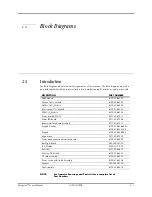
The Block Diagrams indicate the internal organization of the instrument. The block diagrams are used to
gain both familiarity with the instrument and to locate malfunctioning PC boards as readily as possible.
NOTE:
See Isometric Drawings and Parts List for a complete list of
Part Numbers.
DESCRIPTION
PART NUMBER
NIBP Module
6100-30-86329
Masimo SpO
2
Module
6100-30-86335
Nellcor SpO
2
Module
6100-30-86336
Microstream CO
2
Module
6100-30-86333
DPM CO
2
Module
6100-30-86334
Power board(AC/DC)
9211-30-87311
Alarm LED Board
9211-30-87306
Battery interface board assembly
9211-30-87331
Keypad Overlay
6100-20-86264-XX or
6100-20-86341-XX
Keypad
6100-20-86265-XX
Main board
9211-20-87303
Power management and interface board
6100-20-86294
Back light board
022-000001-00
LCD Display
0000-10-11092
Recorder
6101-30-46619
Wireless AP Module
6100-30-86332
CF card assembly
6100-30-86330
Power Switch with Cable Assembly
6100-21-86306
Speaker
020-000001-00
Fan Assembly
6100-21-86315

