A-13
ELECTRICAL SAFETY INSPECTION FORM
Location: Technician:
Equipment: Control
Number:
Manufacturer: Model:
SN:
Measurement equipment /SN:
Date of Calibration:
INSPECTION AND TESTING
Pass/Fail
Limit
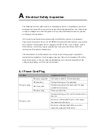
1
Power Cord Plug
2
Device Enclosure and Accessories
3 Device
Labeling
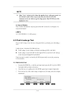
4
Protective Earth Resistance
____
Ω
Max
0.2
Ω
Normal
condition(NC)
____
μ
A
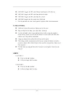
5
Earth
Leakage
Single Fault
condition(SFC)
____
μ
A
Max:
NC: 300
μ
A(refer to
UL60601-1) *
NC: 500
μ
A(refer to
IEC60601-1) *
SFC: 1000
μ
A
□
BF____
μ
A
Normal
condition(NC)
□
CF____
μ
A
□
BF____
μ
A
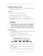
6
Patient
Leakage
Current
Single Fault
condition(SFC)
□
CF____
μ
A
Max:
CF applied part:
NC:10
μ
A, SFC: 50
μ
A
BF applied part:
NC:100
μ
A, SFC:
500
μ
A
□
BF____
μ
A
7
Mains on Applied Part Leakage
□
CF____
μ
A
Max:
CF applied part: 50
μ
A
BF applied part:
5000
μ
A
□
BF____
μ
A
Normal condition(NC)
□
CF____
μ
A
□
BF____
μ
A
8
Patient
Auxiliary
Current
Single Fault
condition(SFC)
□
CF____
μ
A
Max:
CF applied part:
NC:10
μ
A, SFC: 50
μ
A
BF applied part:
NC:100
μ
A, SFC:
500
μ
A
Note: The equipment sold to the United States shall comply with the requirement of
UL60601-1; others shall comply with the requirement of IEC60601-1.
Name/ Signature: __________________________ Date:_____________________________
Summary of Contents for BeneView T5
Page 1: ...DPM 6 Patient Monitor Service Manual ...
Page 2: ......
Page 4: ...II FOR YOUR NOTES ...
Page 12: ...6 FOR YOUR NOTES ...
Page 16: ...1 4 FOR YOUR NOTES ...
Page 32: ...2 16 FOR YOUR NOTES ...
Page 68: ...3 36 FOR YOUR NOTES ...
Page 80: ...4 12 FOR YOUR NOTES ...
Page 126: ...5 46 FOR YOUR NOTES ...
Page 133: ...6 7 6 3 3 12 1 Screen Assembly with anti glare screen Exploded View ...
Page 163: ...6 37 6 6 7 BIS Module Exploded View ...
Page 180: ...6 54 FOR YOUR NOTES ...
Page 204: ...A 14 FOR YOUR NOTES ...
Page 205: ......


