4-5
Power supply failure
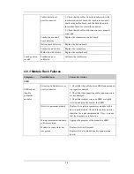
1. Check if the voltage between two contact screws
in any slot reaches 12V DC. If yes and the
parameter module functions properly and the PCB
assembly in SRM might fail.
2. If there is no 12 VDC power sent to the SMR,
check whether the power voltage output to the
USB_Hub board by the power module reaches 12V.
If yes, the fuse of the USB interface board might
blow. Replace the USB_Hub board.
Cable defective or poorly
connected
1. Check that the cable between SMR interface
board and communication board is properly
connected.
2. Check that connecting cables and connectors are
not damaged.
Nios II module loose or failure 1. Check that Nios II module is correctly plug ed
2. If the symptom persists, replace the Nios II
module.
SMR interface board failure
Replace the SMR interface board.
SMR communication board
failure
Replace the SMR communication board.
USB_Hub board failure
Replace the USB_Hub board.
Mother board failure
Replace the mother board.
Integral module rack
Module failure
Replace parameter module. If a new module is identified,
the original one is defective.
Cable defective or
poorly connected
1. Check that the cables from 3-slot module rack
communication board to MPM module rack
communication board, module rack to mother board are
properly connected.
2. Check that connecting cables and connectors are not
damaged.
Wrong communication
board software revision
Upgrade the program of the module or Integral module
rack.
Module (in some slots)
unrecognized
Replace the corresponding module rack communication
board.
Integral module
rack cannot
identify
parameter
modules
Power supply to
integral module rack
abnormal
1. Check if voltage between two contact screws in any slot
reaches 12VDC. If yes and the parameter module
functions, PCB assembly in the SMR might fail.
2. If there is no 12V sent to the integrated module rack,
check that power module output voltage to mother board
reaches 12V DC. If yes, mother board might fail.
Summary of Contents for BeneView T5
Page 1: ...DPM 6 Patient Monitor Service Manual ...
Page 2: ......
Page 4: ...II FOR YOUR NOTES ...
Page 12: ...6 FOR YOUR NOTES ...
Page 16: ...1 4 FOR YOUR NOTES ...
Page 32: ...2 16 FOR YOUR NOTES ...
Page 68: ...3 36 FOR YOUR NOTES ...
Page 80: ...4 12 FOR YOUR NOTES ...
Page 126: ...5 46 FOR YOUR NOTES ...
Page 133: ...6 7 6 3 3 12 1 Screen Assembly with anti glare screen Exploded View ...
Page 163: ...6 37 6 6 7 BIS Module Exploded View ...
Page 180: ...6 54 FOR YOUR NOTES ...
Page 204: ...A 14 FOR YOUR NOTES ...
Page 205: ......


