Adjusting the Tools
6-11
6
Tr
ou
bleshoo
ting
Circle
θ
Correction
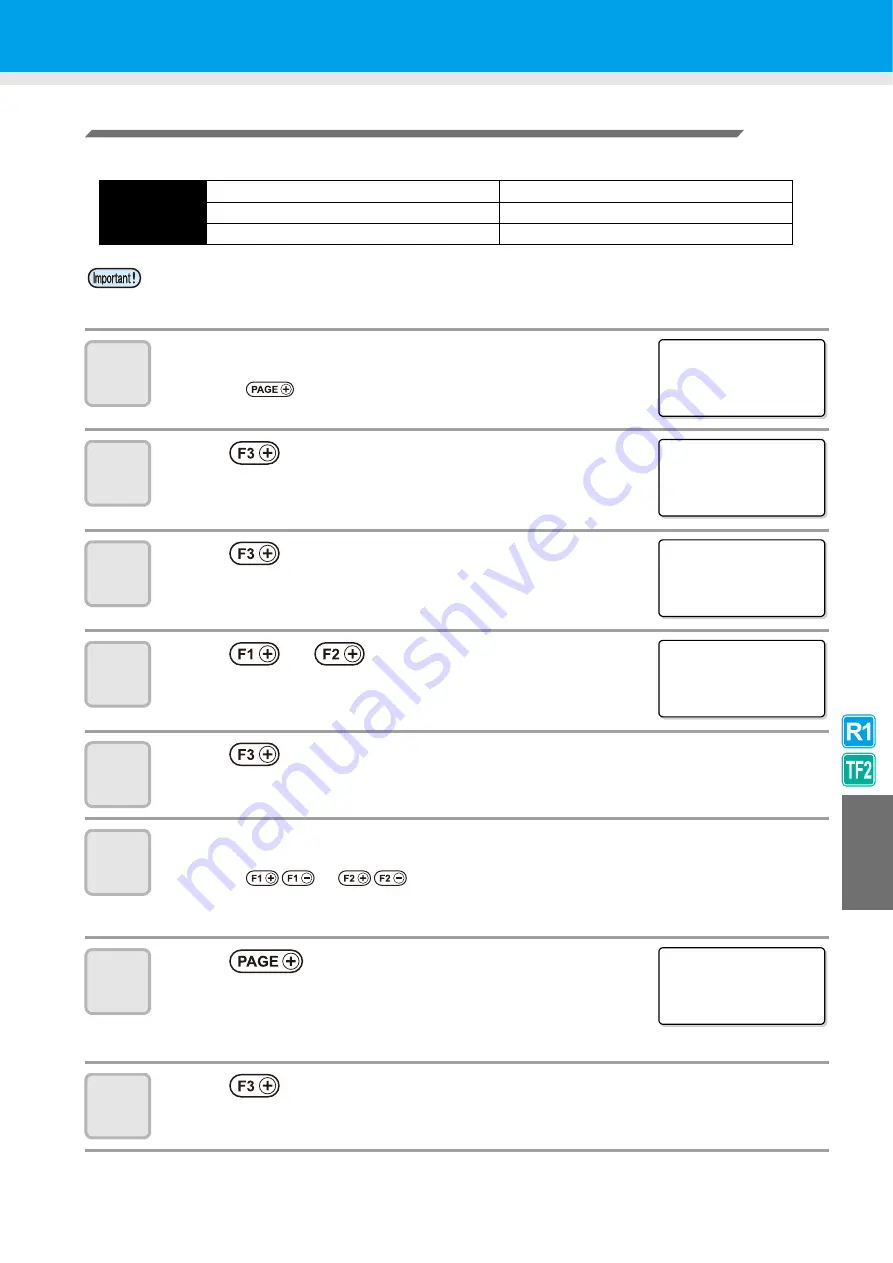
The unit can conduct correction for five circles of different radius.
1
Display the fifth page of the local menu.
• Press
several
times.
2
Press
and
select
TOOL ADJUST.
3
Press
and
select
CIRCLE
θ
.
4
Press
or
and
select the head to set.
5
Press
to start drawing the test pattern.
• Draw the [R < 5] and [5 < R < 10] test patterns.
6
Check and adjust the test pattern.
• Press
or
to make the adjustments.
Set values
:- 20° ~ + 20°
• For details, see P.6-12 "Circle
7
Press
several times to display
the second page of the menu.
8
Press
to start drawing the test pattern.
• Draw the [10<R<20] and [20<R<50] test patterns.
Circle type
for
correction
Radius (R) < 5 mm
20 mm <Radius (R) < 50mm
5 mm <Radius (R) < 10mm
50 mm <Radius (R) < 100mm
10 mm <Radius (R) < 20mm
100 mm <Radius (R)
• In some cases, this cannot be corrected by the CAD system.
• First, set arc
θ
correction to Enable.
If arc
θ
correction is not set to Enable, this offset will not be applied to the drawing (cut).
[ LOCA L ]
5 / 5
RESERVE
- - - >
RESERVE
- - - >
TOOL AD J US T - - - >
< TOOL AD J UST > 1 / 2
B CUT T ER AD J UST >
C ROL L ER AD J UST >
C I RC L E
θ
COR
>
<C I RCL E
θ
>
1 / 1
B HEAD
- >
C HEAD
- >
<C I RCL E
θ
>
1 / 4
R< 5
+ 0 . 0 ° >
5 <R< 1 0
+ 0 . 0 ° >
T ES T PA T T ERN
- >
<C I RCL E
θ
>
2 / 4
1 0 <R< 2 0
+ 0 . 0 ° >
2 0 <R< 5 0
+ 0 . 0 ° >
T ES T PA T T ERN
- >
Summary of Contents for CF3-1610
Page 7: ...vi ...
Page 110: ...3 20 ...
Page 124: ...4 14 ...
Page 164: ...6 30 ...
Page 165: ...D201768 14 29062009 ...
Page 166: ...NH FW 3 30 Printed in Japan MIMAKI ENGINEERING CO LTD 2009 ...


