Mounting Tools
1-29
1
Setup
6
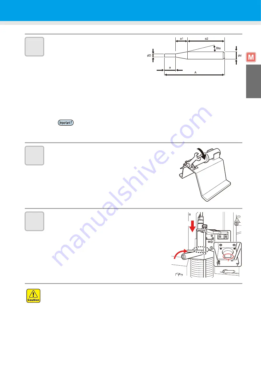
Insert the end mill.
• Use an end mill with A not exceeding 120 mm.
(1) If
a+a1=20 mm or more and a2=50 mm or
more:
As the chuck grasps the end mill in the range
a2, fully push the end mill into the spindle and tighten the chuck.
(2) If a+a1=20 mm or less and a2 is either less or greater than 50mm:
Adjust a + a1 = 20 mm from the chuck, and tighten the chuck to clamp the end mill in the range a2.
(3) If a + a1 = 20 mm or more and a2 = 50 mm or less:
Adjust the boundary between a1 and a2 at the chuck, and tighten the chuck to clamp the end mill
in the range a2.
7
Tighten the chuck nut.
• Turn the chuck nut clockwise with the 14 mm wrench
supplied.
8
Return the spindle motor to its original
position and tighten the locking lever.
(1)
Insert the spindle motor with the stopper aligned with
the groove on the unit.
(2)
Turn the spindle motor to lock it.
(3)
Turn the locking lever clockwise.
• When mounting the end mill with
φ
6 of the blade in the condition of (1), refer to P.2-12
"Setting the Cutting Conditions" and decrease the round speed. If not decreased, it
could destroy the spindle motor.
Example) When cutting a form board A=120mm Set to 30000rpm in the case of a=63.
•
Take care not to overtighten the locking lever.
Overtightening the locking lever can impair the spindle motor accuracy or the bearing life.
•
Spindle motor tightening guideline
Turn the spindle motor body by hand until it stops turning.
Groove
Clockwise
Insert
Summary of Contents for CF3-1610
Page 7: ...vi ...
Page 110: ...3 20 ...
Page 124: ...4 14 ...
Page 164: ...6 30 ...
Page 165: ...D201768 14 29062009 ...
Page 166: ...NH FW 3 30 Printed in Japan MIMAKI ENGINEERING CO LTD 2009 ...


