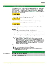
subset is activated. The active parameter subset is displayed at PSS: Actual
param. subset (
Oper/Cycl/Log
menu branch).
10.2.5.1
Checking Differential Protection
For single-side feed, the fault current characteristic crosses the first knee of the
tripping characteristic of the P631 so that the basic threshold value is always
checked.
The current I to which the P631 responds for single-side feed is calculated as
follows:
I
=
I
diff
>
⋅
I
nom
,
z
k
am
,
z
●
z: transformer end (a, b)
●
I
diff>
: set operate value
●
I
nom,z
: nominal current of the P631 for transformer end a, b
●
k
am,z
: amplitude-matching factor of transformer end a, b
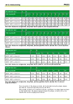
For single-side one-phase or two-phase feed, a vector group-matching factor in
accordance with the set vector group ID needs to be taken into account in
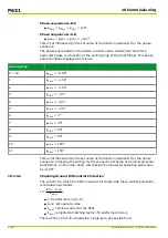
addition to the amplitude-matching factor. The vector group-matching factors are
given in the tables below and the threshold current is calculated as follows:
I
≥
I
diff
>
⋅
I
nom
,
z
k
am
,
z
⋅
k
s
,
y
,
z
●
z: transformer end (a, b)
●
I
diff>
: set operate value
●
I
nom,z
: nominal current of the P631 for transformer end a, b
●
k
am,z
: amplitude-matching factor of transformer end a, b
●
k
s,y,z
: vector group-matching factor (see tables below)
The differential and restraining currents formed by the P631 are displayed as
measured operating data. They aid in assessing whether the connection of the
P631 to the system current transformers and the setting of the vector group ID
are correct. The tables below give the factors ks which serve to calculate the
differential current for single-side feed. The display of differential and restraining
currents is prevented, however, if they fall below minimum thresholds that can
be set by the user.
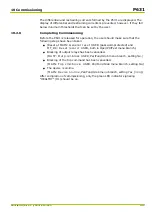
I
d,y
= k
am,z
·k
s,y,z
·I
test,x
●
x: phase A, B or C
●
z: transformer end (a, b)
●
measuring system 1, 2 or 3
●
I
d,y
: differential current as displayed
●
k
am,z
: amplitude-matching factor of transformer end a, b
●
k
s,y,z
: vector group-matching factor (see tables below)
●
I
test,x
: test current phase A, B or C
In evaluating the test results, one should be aware that the P631 will trip as
follows, if a value of I
diff>>
or I
diff>>>
is exceeded.
●
I
diff>>
exceeded: Trip regardless of the inrush and overfluxing restraint;
●
I
diff>>>
exceeded: Trip regardless of the restraining current and regardless
of all other restraints.
P631
10 Commissioning
10-6
P631/EN M/R-11-C // P631-310-650
Summary of Contents for P631
Page 2: ......
Page 4: ......
Page 7: ...Changes after going to press...
Page 8: ......
Page 16: ...P631 Table of Contents 8 P631 EN M R 11 C P631 310 650...
Page 56: ...P631 2 Technical Data 2 28 P631 EN M R 11 C P631 310 650...
Page 236: ...P631 3 Operation 3 180 P631 EN M R 11 C P631 310 650...
Page 246: ...P631 4 Design 4 10 P631 EN M R 11 C P631 310 650...
Page 266: ...P631 5 Installation and Connection 5 20 P631 EN M R 11 C P631 310 650...
Page 276: ...6 8 Configurable Function Keys P631 6 Local Control HMI 6 10 P631 EN M R 11 C P631 310 650...
Page 548: ...P631 10 Commissioning 10 10 P631 EN M R 11 C P631 310 650...
Page 568: ...P631 12 Maintenance 12 8 P631 EN M R 11 C P631 310 650...
Page 570: ...P631 13 Storage 13 2 P631 EN M R 11 C P631 310 650...
Page 572: ...P631 14 Accessories and Spare Parts 14 2 P631 EN M R 11 C P631 310 650...
Page 576: ...P631 15 Order Information 15 4 P631 EN M R 11 C P631 310 650...
Page 582: ...P631 A2 Internal Signals A2 4 P631 EN M R 11 C P631 310 650...
Page 608: ...P631 A4 Telecontrol Interfaces A4 18 P631 EN M R 11 C P631 310 650...
Page 637: ......

