
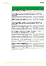


Parameter
Address
Default
Min
Max
Unit
Logic Diagram
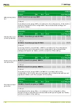
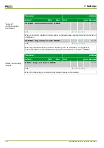
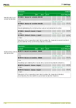
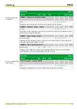
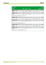
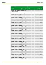
Measuring-circuit
monitoring
MCM_1: General enable USER
031 146
0: No
[spacer]
MCM_2: General enable USER
031 147
0: No
[spacer]
Enabling or disabling the measuring-circuit monitoring function.
[spacer]
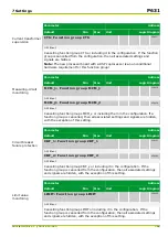
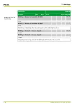
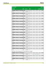
MCM_1: Select. meas. input
031 150
0: End a
[spacer]
MCM_2: Select. meas. input
031 151
1: End b
[spacer]
Assigning measuring-circuit monitoring functions to ends a and b.
P631
7 Settings
7-82
P631/EN M/R-11-C // P631-310-650
Summary of Contents for P631
Page 2: ......
Page 4: ......
Page 7: ...Changes after going to press...
Page 8: ......
Page 16: ...P631 Table of Contents 8 P631 EN M R 11 C P631 310 650...
Page 56: ...P631 2 Technical Data 2 28 P631 EN M R 11 C P631 310 650...
Page 236: ...P631 3 Operation 3 180 P631 EN M R 11 C P631 310 650...
Page 246: ...P631 4 Design 4 10 P631 EN M R 11 C P631 310 650...
Page 266: ...P631 5 Installation and Connection 5 20 P631 EN M R 11 C P631 310 650...
Page 276: ...6 8 Configurable Function Keys P631 6 Local Control HMI 6 10 P631 EN M R 11 C P631 310 650...
Page 548: ...P631 10 Commissioning 10 10 P631 EN M R 11 C P631 310 650...
Page 568: ...P631 12 Maintenance 12 8 P631 EN M R 11 C P631 310 650...
Page 570: ...P631 13 Storage 13 2 P631 EN M R 11 C P631 310 650...
Page 572: ...P631 14 Accessories and Spare Parts 14 2 P631 EN M R 11 C P631 310 650...
Page 576: ...P631 15 Order Information 15 4 P631 EN M R 11 C P631 310 650...
Page 582: ...P631 A2 Internal Signals A2 4 P631 EN M R 11 C P631 310 650...
Page 608: ...P631 A4 Telecontrol Interfaces A4 18 P631 EN M R 11 C P631 310 650...
Page 637: ......