
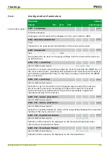


7.1.2
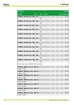
Configuration Parameters
Parameter
Address
Default
Min
Max
Unit
Logic Diagram
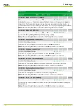
Local control panel
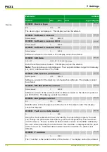
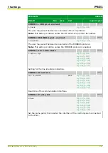
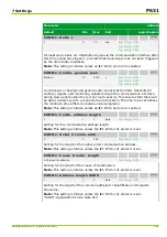
LOC: Language
003 020
2: Reference language
[spacer]
Language in which texts will be displayed on the user interface (HMI).
[spacer]
LOC: Decimal delimiter
003 021
1: Dot
[spacer]
Character to be used as decimal delimiter on the local control panel.
[spacer]
LOC: Password
003 035
1234
0
4444
[spacer]
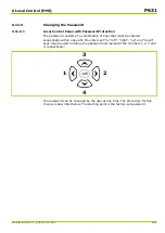
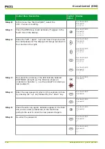
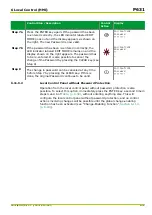
The password to be used for changing settings from the local control panel can
be defined here.
[spacer]
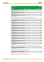
LOC: Fct. reset key
005 251
060 000: MAIN: Without function
[spacer]
Selection of counters and memories that are reset by pressing the RESET key on
the local control panel. (Resetting LED indicators and measured event values is
permanently assigned internally, so that they are always reset when the RESET
key is pressed.)
[spacer]
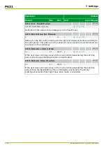
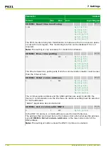
LOC: Fct. read key
080 110
060 000: MAIN: Without function
[spacer]
Selection of up to 16 functions to be triggered when pressing the read key.
Event counters and event recordings are offered for selection. If several
functions have been selected then they will be sequentially triggered by
repeated pressing of the read key.
[spacer]
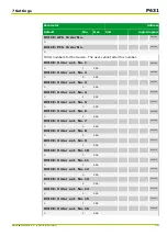
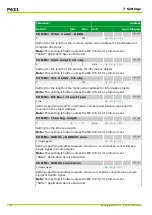
LOC: Fct. menu jmp list 1
030 238
060 000: MAIN: Without function
[spacer]
LOC: Fct. menu jmp list 2
030 239
060 000: MAIN: Without function
[spacer]
Selection of specified functions which will be sequentially displayed by repeated
reading of the menu jump list 1 (or 2).
[spacer]
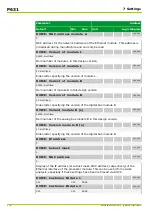
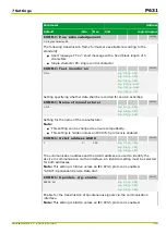
LOC: Fct. Operation Panel
053 007
060 000: MAIN: Without function
[spacer]
Definition of the values to be displayed on the Measured Value Panel also
referred to as the Operation Panel.
[spacer]
LOC: Fct. Overload Panel
053 005
060 000: MAIN: Without function
[spacer]
Definition of the values to be displayed on the Overload Panel.
7 Settings
P631
P631/EN M/R-11-C // P631-310-650
7-11
Summary of Contents for P631
Page 2: ......
Page 4: ......
Page 7: ...Changes after going to press...
Page 8: ......
Page 16: ...P631 Table of Contents 8 P631 EN M R 11 C P631 310 650...
Page 56: ...P631 2 Technical Data 2 28 P631 EN M R 11 C P631 310 650...
Page 236: ...P631 3 Operation 3 180 P631 EN M R 11 C P631 310 650...
Page 246: ...P631 4 Design 4 10 P631 EN M R 11 C P631 310 650...
Page 266: ...P631 5 Installation and Connection 5 20 P631 EN M R 11 C P631 310 650...
Page 276: ...6 8 Configurable Function Keys P631 6 Local Control HMI 6 10 P631 EN M R 11 C P631 310 650...
Page 548: ...P631 10 Commissioning 10 10 P631 EN M R 11 C P631 310 650...
Page 568: ...P631 12 Maintenance 12 8 P631 EN M R 11 C P631 310 650...
Page 570: ...P631 13 Storage 13 2 P631 EN M R 11 C P631 310 650...
Page 572: ...P631 14 Accessories and Spare Parts 14 2 P631 EN M R 11 C P631 310 650...
Page 576: ...P631 15 Order Information 15 4 P631 EN M R 11 C P631 310 650...
Page 582: ...P631 A2 Internal Signals A2 4 P631 EN M R 11 C P631 310 650...
Page 608: ...P631 A4 Telecontrol Interfaces A4 18 P631 EN M R 11 C P631 310 650...
Page 637: ......