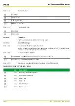


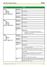


Version
Changes
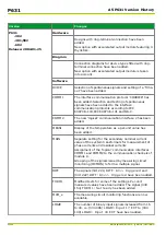
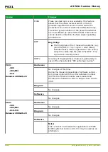
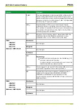
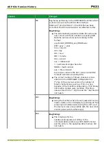
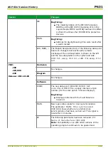
SFMON
Addendum:
As of version –605 the “memory function” for the
warning signal memory may be set. After the
associated timer stage has elapsed, a renewed
occurrence of a warning is processed the same way as
if it where a first occurrence.
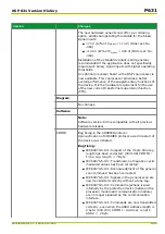
The configuration table of the user defined alarm
condition has been accomplished by the instantaneous
and timed outputs 30…32(t) of the programmable
LOGIC:
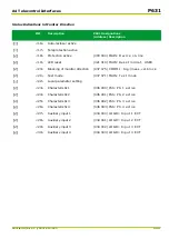
●
(098 053) SFMON: Output 30 ~ (042 090)
LOGIC: Output 30
●
(098 054) SFMON: Output 30 (t) ~ (042 091)
LOGIC: Output 30 (t)
●
(098 055) SFMON: Output 31 ~ (042 092)
LOGIC: Output 31
●
(098 056) SFMON: Output 31 (t) ~ (042 093)
LOGIC: Output 31 (t)
●
(098 057) SFMON: Output 32 ~ (042 094)
LOGIC: Output 32
●
(098 058) SFMON: Output 32 (t) ~ (042 095)
LOGIC: Output 32 (t)
These logic outputs are included in the warning signals
by setting SFMON: Fct. assign. warning and they
are also recorded in the monitoring signal memory.
These signals can be used to create an alarm signal
under complex application conditions. This signaling
has no influence on the device's operation (i.e. no
warm restart or blocking).
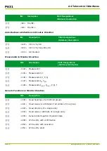
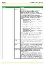
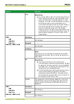
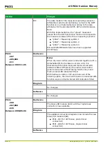
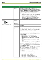
FT_RC
The recording duration for binary tracks is now limited
to 1 minute in order to prevent recording of endless
events.
MAIN
Priority control of clock synchronization is now settable.
Positive- and negative-sequence currents from all ends
are now continuously calculated and displayed as
measured operating data (primary and per-unit values).
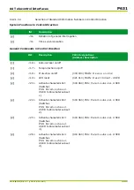
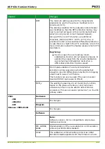
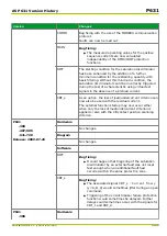
OL_RC, FT_RC Overload and fault recording now have a joint and
complete list of possible entries (merged list of all
previous signals).
In practice it became apparent that limitations with
regard to possible entries in both recording memories
would bring no advantages but make analyzing more
difficult, as both recording memories could be open at
the same time (e.g. a thermal overload situation could
lead to a loss of insulation which would cause a fault).
P631
A5 P631 Version History
A5-6
P631/EN M/R-11-C // P631-310-650
Summary of Contents for P631
Page 2: ......
Page 4: ......
Page 7: ...Changes after going to press...
Page 8: ......
Page 16: ...P631 Table of Contents 8 P631 EN M R 11 C P631 310 650...
Page 56: ...P631 2 Technical Data 2 28 P631 EN M R 11 C P631 310 650...
Page 236: ...P631 3 Operation 3 180 P631 EN M R 11 C P631 310 650...
Page 246: ...P631 4 Design 4 10 P631 EN M R 11 C P631 310 650...
Page 266: ...P631 5 Installation and Connection 5 20 P631 EN M R 11 C P631 310 650...
Page 276: ...6 8 Configurable Function Keys P631 6 Local Control HMI 6 10 P631 EN M R 11 C P631 310 650...
Page 548: ...P631 10 Commissioning 10 10 P631 EN M R 11 C P631 310 650...
Page 568: ...P631 12 Maintenance 12 8 P631 EN M R 11 C P631 310 650...
Page 570: ...P631 13 Storage 13 2 P631 EN M R 11 C P631 310 650...
Page 572: ...P631 14 Accessories and Spare Parts 14 2 P631 EN M R 11 C P631 310 650...
Page 576: ...P631 15 Order Information 15 4 P631 EN M R 11 C P631 310 650...
Page 582: ...P631 A2 Internal Signals A2 4 P631 EN M R 11 C P631 310 650...
Page 608: ...P631 A4 Telecontrol Interfaces A4 18 P631 EN M R 11 C P631 310 650...
Page 637: ......